TB6575/TB8575 SUITEPRO™ DIGITAL FAN COIL THERMOSTATS
62-0278—13 12
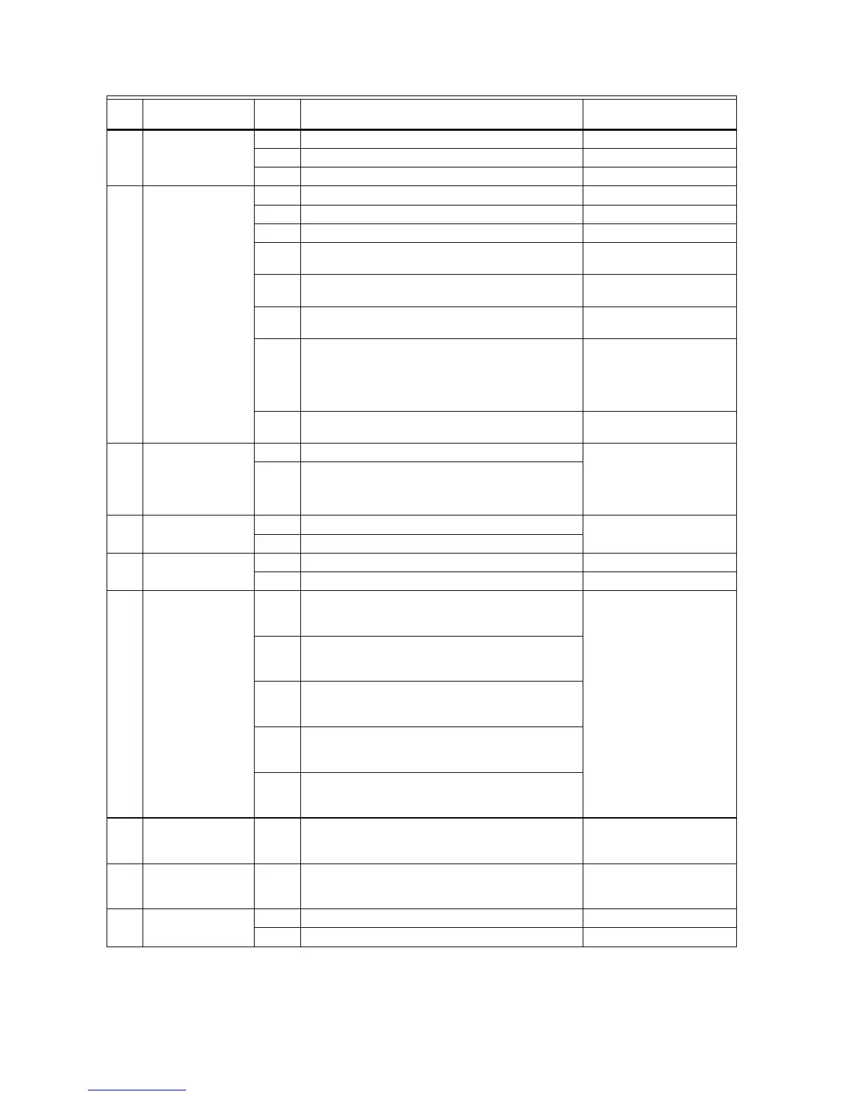
Table 4. Installer Setup (IS) Codes and Options.
IS
Code Code Description
Option
Value
Option Description (Default value shown in
Bold) Notes
1 Line Voltage
Selection
0 120 Vac power supply (Default)
1 240 Vac power supply
2 277 Vac power supply
2 System Type 0 Heat only
1 Cool only
2 Two pipes: Heat or Cool; Manual Changeover
3 Two pipes: Heat or Cool; Seasonal Changeover
(requires optional pipe sensor)
4 Four pipes: Manual Changeover TB6575A, TB6575C and
TB8575A only
5 Four pipes: Auto Changeover TB6575A, TB6575C and
TB8575A only
6 Two pipes: Heat or Cool; with Auxiliary Heat
(requires optional pipe sensor).
Allows auxiliary heat to turn
on when pipes have cold
water
(TB6575A, TB6575C and
TB8575A only).
7 Four pipes: Manual and Auto Changeover
(Default)
TB6575A, TB6575C and
TB8575A only
2.5 Fan On/Off
Selection for Aux
Heat On
0 Fan ON when Auxiliary Heat is on (Default) Enables or disables the
auto fan operation when
Auxiliary Heat is On
(TB6575A, TB6575C and
TB8575A only).
1 Fan OFF when Auxiliary Heat is on
3 Valve Output Type 0 N.C. (normally closed) - ON/OFF (Default)
1 N.O. (normally open) - ON/OFF
4Sensor Type 0 Onboard Sensor (Default)
1 Remote Sensor (TR21 or other 20K Ohm sensor)
5 Pipe Sensor 0 Default mode is Heat:
N.O. (normally open) Input.
Only displays when system type 3 or 6 is selected.
The Pipe Sensor code
automatically displays
based on the System Type
(IS code #2) selection. For
example, only when you
select the value 3 or 6 for
the System Type, will the
Pipe Sensor code and its
values display.
• Pipe sensor will flash on
display screen if analog
input (#4) is lost.
• Pipe sensor status and
water temperature can be
checked in test mode (see
“Installer Test (IT) Mode” on
page 15 for details)
1 Default mode is Cool:
N.O. (normally open) Input.
Only displays when system type 3 or 6 is selected.
2 Default mode is Heat:
N.C. (normally closed) Input.
Only displays when system type 3 or 6 is selected.
3 Default mode is Cool:
N.C. (normally closed) Input.
Only displays when system type 3 or 6 is selected.
4 Analog input (Default). NTC20K, whose curve is
the same as TR21.
Only displays when system type 3 or 6 is selected.
6 Pipe Sensor
Threshold for
Cooling
50 to
72
Range is 50°F to 72°F. Default is 60°F. Changes to Cool when pipe
temperature is below
threshold.
7 Pipe Sensor
Threshold for
Heating
75 to
90
Range is 75°F to 90°F. Default is 80°F. Changes to Heat when pipe
sensor temperature is
above threshold.
8 Temperature Scale 0 Degrees Fahrenheit (°F); Default.
1 Degrees Celsius (°C).
 Loading...