GB
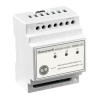
Wireless
I/O Unit T2
http://www.hls-nordic.com
Dimensional drawings:
Wall mounting installation:
Installation on a DIN-rail:
Honeywell Life Safety AS, Postboks 263, 1372 Asker
Step 1. With the screws properly fastened, drill one of the holes A, B or C (fig. 1). If you choose hole A or B
the drill size must be 12 Ø and place the glands. If you choose hole C you can drill pattern of the
hole. Follow the same step for the other side of the device.
Step 3. Drill the 2 holes (fig. 3) and use the mounting accessories to mount the device.
Step 2. Unfasten the 2 screws (fig. 2) and remove the front cover.
Step 4. Install the cables (and the glands if needed) and perform the electrical connections. (NOTE: Use
1 power input only, either 230 VAC or 24 VDC.)
Step 5. Reinstall the removed parts of step 2 and power on the device.
70mm 60mm
90mm
IN1
IN2
NC
NO
N
+
-
L
NO
NC
C
C
~230V IN
24VDC IN
REL2
REL1
1
1
2
2
3
4
B
A
C
IN1
IN2
NC
NO
N
+
-
L
NO
NC
C
C
~230V IN
24VDC IN
REL2
REL1
(NOTE: Use 1 power input only, either 230 VAC or 24 VDC.) Power on the device.
Step 1. Pull the mounting clips to open and mount the device on the DIN rail.
Step 2. Install the cables and perform the electrical connections.
In case you want to install the device without the including box: