R Power [1]
Rc [R+Rc joined by Slider Tab] [2]
Y Compressor contactor (stage 1)
C 24VAC common [3]
O/B Changeover valve [7]
G Fan relay
Aux Auxiliary heat
E Emergency heat relay
Y2 Compressor contactor (stage 2 – if needed)
L Heat pump fault input
S Outdoor sensor
S Outdoor sensor
NOTES
Wire specifications: Use 18- to 22-gauge thermostat wire. Shielded cable is not required.
1. Power supply. Provide disconnect means and overload protection as required.
2. Move R-Slider Tab on UWP to the R setting. For more information, see “Setting Slider Tabs” on
page 3
3. Optional 24VAC common connection.
4. In Installer Setup, set system type to 2Heat/2Cool Conventional.
5. In Installer Setup, set changeover valve to O (for cool changeover) or B (for heat changeover).
6. In ISU set Heat system type to Heat pump. 1 compressor and 1 stage of backup heat.
7. In ISU set Heat system type to Heat pump. 2 compressors and 0 stage of backup heat.
8. In ISU set Heat system type to Heat pump. 2 compressors and 1 stage of backup heat.
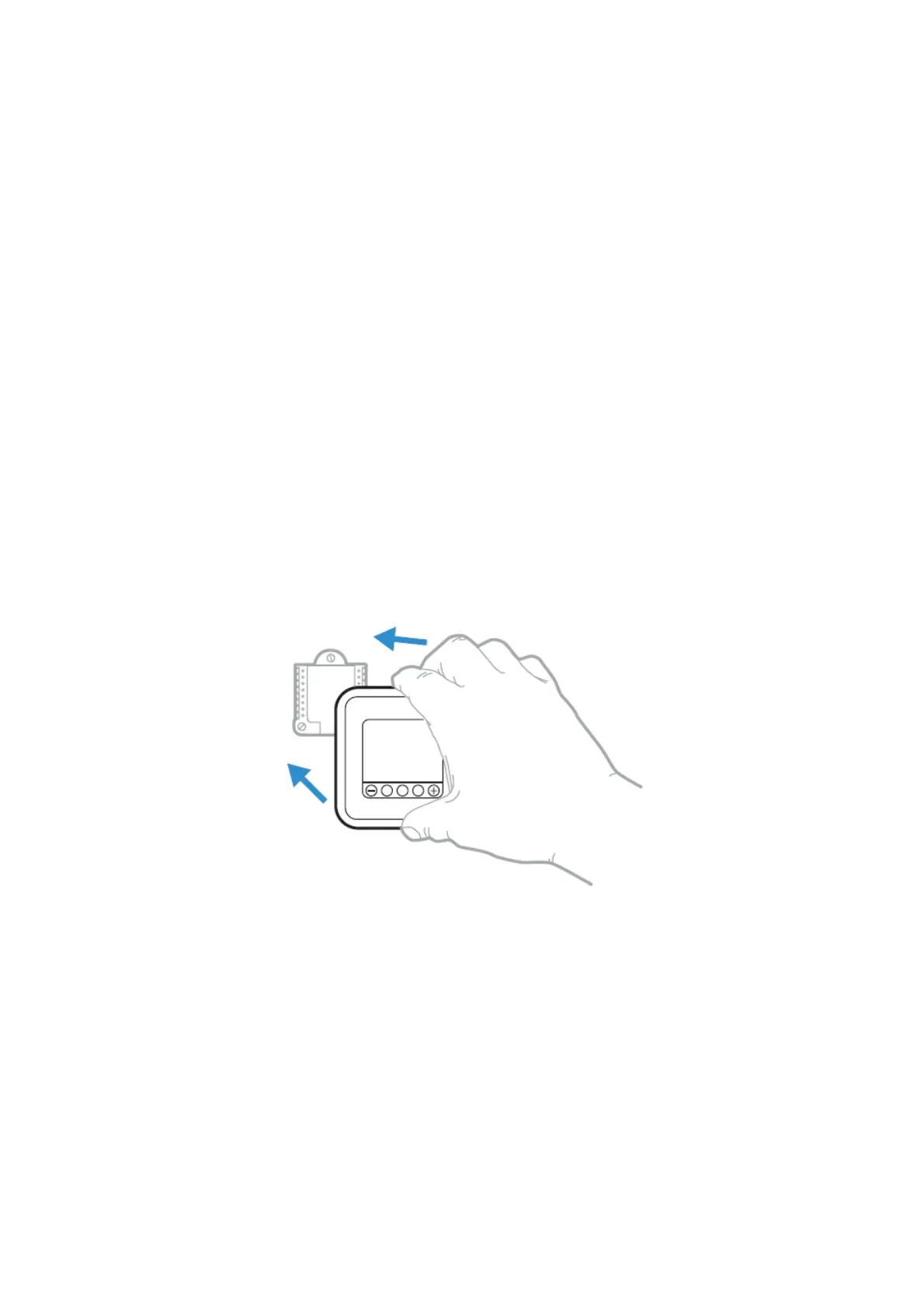
Thermostat mounting
1. Push excess wire back into the wall opening.
2. Close the UWP door. It should remain closed without bulging.
3. Align the UWP with the thermostat, and push gently until the thermostat snaps in place.
4. Turn the power on at the breaker box or switch.
System operation settings
 Loading...