5 63-2489
T775A,B,C,D
SPECIFICATIONS • INSTALLATION
ACCESSORIES:
T775A,B:
A775A1003 Temperature Sensor Simulator.
C7100C Duct Mount Averaging Sensor.
198212CA Water Resistant Sensor.
203401B Water Tight Sensor.
T7047C1090 Wall Mounted Sensor Case.
107324A Bulb Holder, duct insertion.
121371A Copper Immersion Well.
121371E Stainless Steel Well.
107048 Heat Conduction Compound, 4 ounce.
C7043A1098 Case and Immersion Well for running
conduit to sensor.
T775C,D:
121371A Copper Immersion Well.
121371E Stainless Steel Well.
107408 Heat Conduction Compound, 4 ounce.
C7043A1098 Case and Immersion Well for running
conduit to sensor.
Installation
WHEN INSTALLING THIS PRODUCT…
1. Read these instructions carefully. Failure to fol-
low them could damage the product or cause a hazardous
condition.
2. Check the ratings given in the instructions and on
the product to make sure the product is suitable for your
application.
3. Installer must be a trained, experienced service
technician.
4. After installation is complete, check out the product
operation as provided in these instructions.
WARNING
Disconnect power before installation to prevent
electrical shock or equipment damage.
LOCATION AND MOUNTING
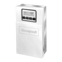
Mount the controller on any convenient interior location
using the two mounting holes provided on the back of the
metal enclosure (mounting screws are not provided and
must be obtained separately). Use controller dimensions in
Fig. 1 (T775A,B) or Fig. 2 (T775C,D) as a guide.
SENSOR LOCATION
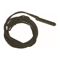
The 193987GA Sensor can be located up to 1000 feet
(304 meters) from the T775 using standard AWG 18/2
unshielded wire. For cable runs greater than 25 feet shielded
cable is recommended. See Fig. 5. It may be located on pipes,
in an immersion well, in a wall-mounted case or on a bulb
holder. See Fig. 6. The 193987GA is not a water tight or
water resistant sensor. For wet applications, see the Accesso-
ries list in the Specifications section.
Multiple sensors can be parallel-series wired to sense
average temperatures in large spaces.
To maintain control accuracy, the number of sensors
parallel-series wired must be of the n
2
power (for example, 4,
9, 16, etc.). See Fig. 7.
SENSOR MOUNTING
Sensors can be mounted on a wall or panel for sensing
space temperature (Fig. 6), strapped to a pipe or inserted in a
well (Fig. 8) for hot/cold water sensing, or taped to a standard
cap or bulb holder for duct air sensing. To prevent moisture
or condensation entering the sensor through the leadwire
holes, mount the sensor with the lead wires exiting the bot-
tom of the sensor.
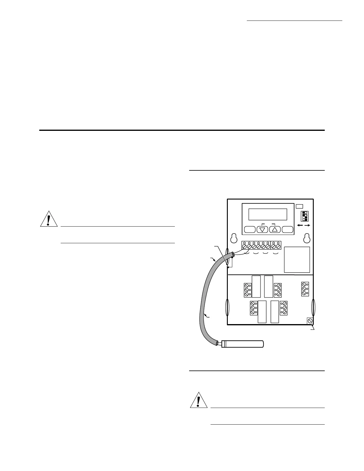
Fig. 5—Using shielded cable for cable runs
longer than 25 feet.
NOTE: Use heat conductive compound in immersion wells.
See optional Accessories in the Specifications section.
CAUTION
Make sure that metal tube of sensor does not short
against T terminals in wall-mounted case.
SELECT
SET
ENTER
12
3
4
1
2
3
4
SA SB
C \ F
SENSOR
A
SENSOR
B
TOD
24V
5
6
120V
COM
240V
OUTPUT 2
OUTPUT 1
OUTPUT 3
OUTPUT 4
NO
COM
NC
NO
COM
NC
NC
COM
NO
7
8
NC
COM
NO
T775
GROUND
SHIELD
TO T775
CABLE OR TO
GROUNDING
SCREW
SHIELDED
CABLE
SHIELDED
CABLE
GROUNDING SCREW
NOTE: DO NOT GROUND
SHIELDED CABLE AT
SENSOR END.
NOTE: TO MINIMIZE NOISE PICKUP, MAKE CONNECTION
FROM SHIELDED CABLE AS CLOSE TO
SENSOR BODY AS POSSIBLE.
SENSOR
M7430
 Loading...