9 63-2489
T775A,B,C,D
DESCRIPTION/OPERATION
Cooling Mode:
• Stage One: Energized at 70°F.
The T775B,D have dual sensor inputs and allow two
separate controllers to exist within one enclosure. Selection
of the stage parameters (operation mode, setpoints, and
differentials) is the same as for a single sensor device after
each stage is assigned its operating sensor. This assignment
is hardware driven via a four position DIP switch. An
explanation of the DIP switch assignments appears in Fig. 9.
See Fig. 3 and 4 for the DIP switch location.
CONTACT CLOSURE OVERRIDE INPUT
A two-terminal input is provided to allow the user to
override a relay-energized condition on all outputs by using
a contact closure between terminal pins 3 and 4 of the
terminal block for the sensor input shown in Fig. 3 and 4.
This can be achieved manually or by using an EMS control-
ler or time clock with normally open contacts (W7505 or
S7005, for example).
When this override is active, the display will show the
number of the stages that would be energized and the words
STAGE ENERGIZED will flash on the display. The ener-
gized stages will then be de-energized until the override
returns to inactive (Off).
°F/°C SELECTION
A single jumper plug controls °F/°C indication of the
displayed temperature value. The location of this jumper is
shown in Fig. 3 and 4. The unit is shipped with the jumper
installed in the °F mode. To operate the device in the °C
mode, remove the jumper. Replacing the jumper will rein-
state the °F mode.
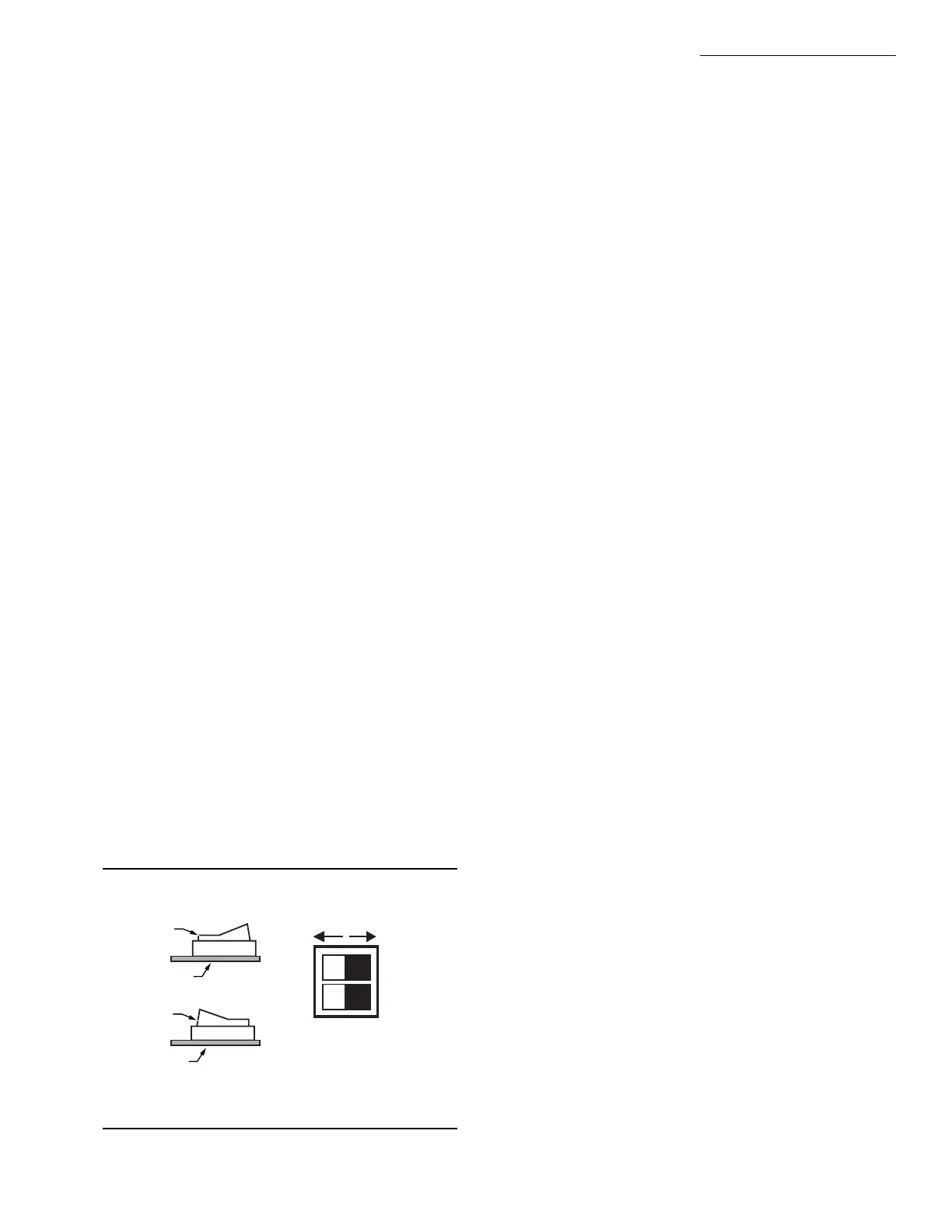
DIP SWITCH SELECTIONS
On the T775B and D, the DIP switches are provided for
assignment of each relay output stage to its operating sensor.
If an individual switch is depressed toward its correspond-
ing load number (1 through 4 on DIP switch) or to the right,
Sensor B will be the controlling sensor for that output stage.
If an individual switch is depressed to the left, Sensor A will
be the controlling sensor for the output stage. An example of
the switches and their corresponding positioning is shown in
Fig. 9.
Fig. 9—DIP switch settings for sensor selection.
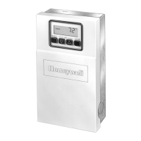
KEYPAD PROGRAMMING AND DISPLAY
The T775 utilizes a Liquid Crystal Display (LCD) for
interactive prompting during programming and display of
sensed and assigned setpoint and differential values. User
programming of the T775 is accomplished through the four
programming keys.
Programming Keys
The four programming keys are the Select, Up arrow,
Down arrow and Enter keys.
• Select key sequentially prompts the user about what
parameter is being displayed: setpoint, differential,
stage energized, heat or cool (operation mode), 1,2,3,4
(indicating assigned stage). After the last parameter
value is viewed, pressing the Select key will again
display the control values from the beginning of the
display loop.
• Up and Down arrow keys allow the displayed param-
eter to be increased or decreased. After pressing the
Select key, a control value can be changed by using the
arrow keys. Control values will be increased or de-
creased by 1°F or 1°C for each time the arrow key is
depressed.
• Enter key places the new value into the memory of the
microprocessor.
IMPORTANT: A control value or operation will not be
entered into the memory of the microprocessor until
the Enter key is pressed.
• Press the Select and Enter keys at the same time to
change the control algorithm from heating to cooling
or from cooling to heating. The heating and cooling
parameters are not displayed during the normal Select
key sequences. The only parameters displayed after
pressing the Select and Enter keys at the same time
will be the stage indication and the word, heat or cool.
To change the operation from heating to cooling or
vice versa for a desired output stage, use the arrow
keys. Once the mode is changed, pressing the Enter
key is necessary to enter this change into the micropro-
cessor memory. The next stage of heat or cool assign-
ment will appear after the Select key is pressed. When
all stages are programmed, the display will revert back
to sensed temperature and load energized status.
Control values and operation selection will remain in the
device memory even after the power is removed.
Display
Once power is applied or restored to the device, the dis-
play will count down from 210 until the display reads zero,
during which time any previously energized outputs will be
de-energized. This is intended to protect compressors in the
event of a power outage.
To avoid viewing this entire countdown, press the Select
key. The LCD display will now show what it normally reads:
load (sensed) temperature, stages energized, and which sen-
sor (Sensor A or Sensor B) is being read for two sensor
M3292
LOAD 1 IS CONTROLLED BY
SENSOR A WHEN SWITCH IS
DEPRESSED ON THE LEFT
LOAD 2 IS CONTROLLED BY
SENSOR B WHEN SWITCH IS
DEPRESSED ON THE RIGHT
(AS SHOWN)
SENSOR A SENSOR B
LOAD 1
LOAD 2
SIDE VIEW
AB
SWITCH
SWITCH
PWB
PWB
 Loading...