63-2489 6
T775A,B,C,D
INSTALLATION
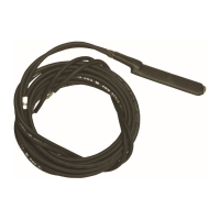
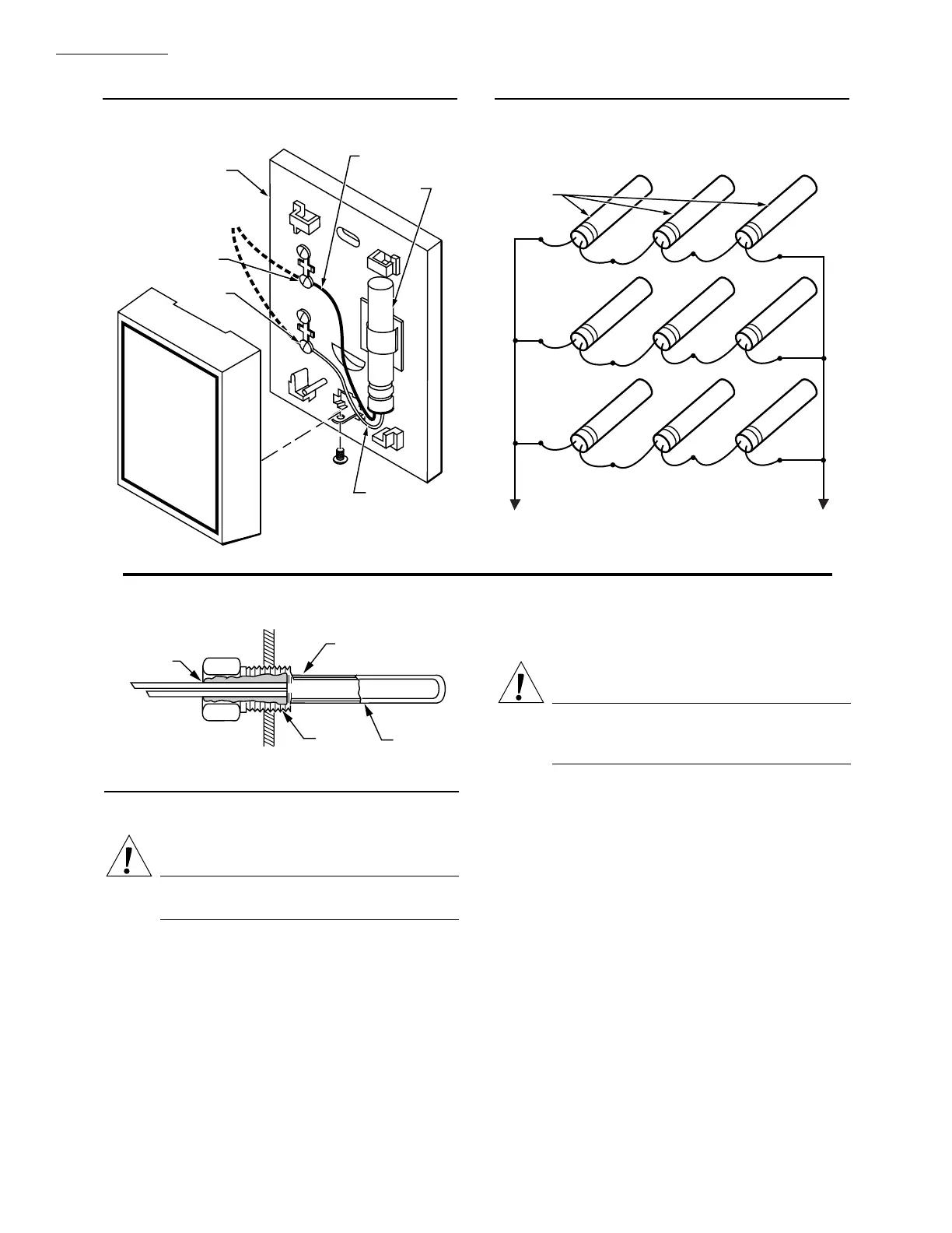
Fig. 6—Sensor mounted on wall.
M8109A
WHITE LEAD
BLACK LEAD
193987GA
SENSOR
T7047C1090
WALLMOUNT SENSOR
CASE (OPTIONAL)
CAUTION: POSITION SENSOR AWAY
FROM SCREW TERMINALS
SCREW
TERMINAL
SCREW
TERMINAL
LEADWIRES
TO T775
Fig. 7—Parallel-series wiring of sensors.
TO T775 CONNECTIONS 1 AND 2 (SENSOR A)
OR 7 AND 8 (SENSOR B)
SENSORS
M7431
Fig. 8—Sensor inserted in immersion well.
M5249
SENSOR PLACED
IN WELL
IMMERSION
WELL
1/2 NPT
COVER SENSOR
LEADS WITH
HEAT CONDUCTIVE
COMPOUND
WIRING
WARNING
Disconnect power before installation to prevent
electrical shock or equipment damage.
Disconnect external power before wiring to prevent elec-
trical shock or equipment damage. All wiring must comply
with applicable codes and ordinances.
IMPORTANT: The T775 is an operating control, not a
limit or safety control. If used in applications requir-
ing safety or limit controls, use a separate safety or
limit control device in conjunction with the T775.
WARNING
Do not use 24 Vac power at terminals 5 and 6 to
power any external loads if 120 Vac or 240 Vac is
used to power the T775.
Refer to Fig. 3 or 4 for locating the appropriate power
inputs, remote sensor input, load output terminals, contact
closure input and sensor selection switch. Access to the
terminals can be gained through standard conduit knockouts
(A through C) located around the perimeter of the enclosure.
NOTE: Hole A should only be used for sensor, low-voltage
and contact closure wiring.
 Loading...