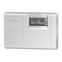
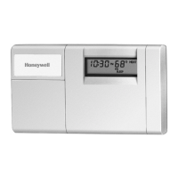
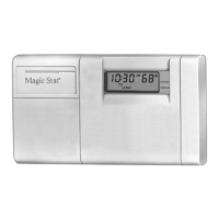
T8112 PROGRAMMABLE THERMOSTAT
68-0170
4
CAUTION
Disconnect power before wiring to prevent electrical
shock or equipment damage.
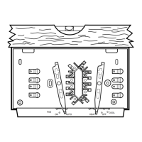
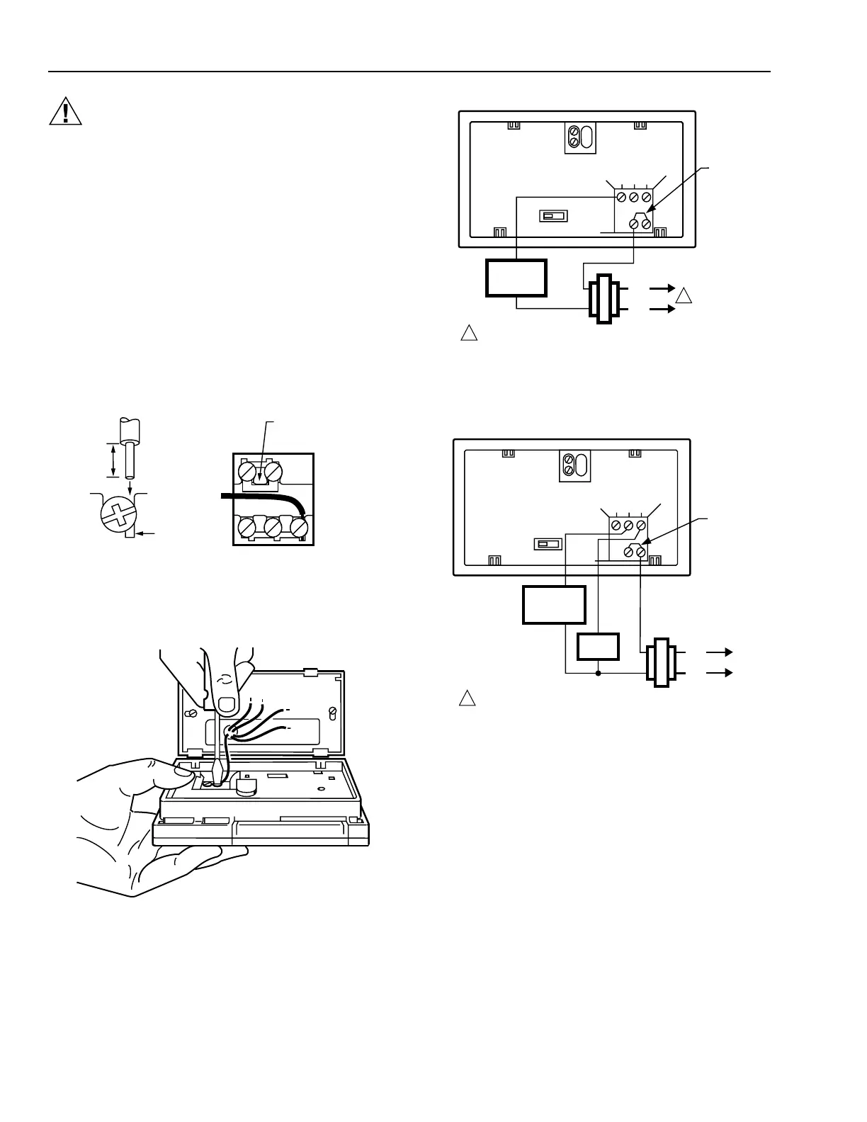
A Connect the system wires to the thermostat. See Fig. 3.
A letter code is located near each terminal for
identification.
NOTE: Hold the thermostat as shown in Fig. 4 to
minimize the need for wire extenders.
B Securely tighten each terminal screw.
C Push excess wire back into the hole.
D Plug the hole with nonflammable insulation to prevent
drafts from affecting thermostat operation.
E Run the required number of wires to the thermostat
location. Refer to Fig. 5 through 8 for typical wiring
diagrams.
F In 5-wire installations only, be sure to remove the factory-
installed jumper connecting the terminals R and Rc.
M1712A
JUMPER (FACTORY-
INSTALLED) REMOVE
IF 5-WIRE SYSTEM
INSERT
STRAIGHT
UNDER
SCREW HEAD
5/16 in.
(8 mm)
STRIP
END OF WIRE
VISIBLE HERE
R
R
c
WY G
Fig. 3. Proper wiring technique.
M3002A
Fig. 4. Holding thermostat while installing.
R
Rc
W Y G
B D
A C
2-WIRE HEAT-ONLY (JUMPER INTACT)
M1709B
L1
(HOT)
L2
POWER SUPPLY. PROVIDE DISCONNECT MEANS AND
OVERLOAD PROTECTION AS REQUIRED.
1
1
HEATING
RELAY OR
VALVE COIL
JUMPER
Fig. 5. 2-wire heat-only application (jumper intact).
R
Rc
W Y G
B D
A C
3-WIRE COOL-ONLY (JUMPER INTACT)
L1
(HOT)
L2
POWER SUPPLY. PROVIDE DISCONNECT MEANS AND
OVERLOAD PROTECTION AS REQUIRED.
1
JUMPER
M848A
COOLING
CONTACTOR
COIL
FAN
RELAY
Fig. 6. 3-wire cool-only application (jumper intact).
 Loading...