2
8. For optimum performance, level the thermostat us-
ing a spirit level or plumb line. Tighten the mounting
screws.
IMPORTANT: An incorrectly leveled thermostat will cause
the temperature control to deviate from setpoint.
9. Replace the thermostat cover.
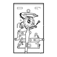
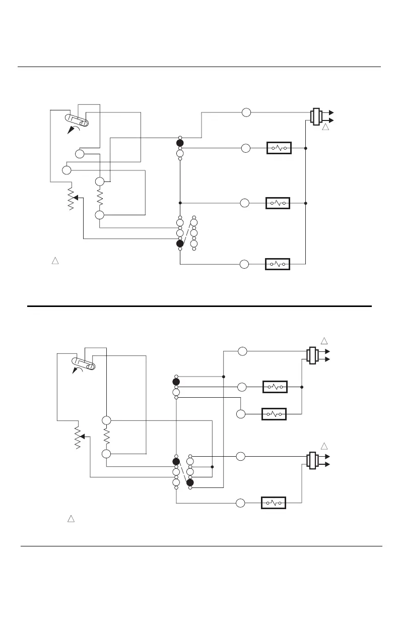
Fig. 2—Internal schematic and typical hookup diagram for single-transformer heating-cooling systems.
Fig. 3—Internal schematic and typical hookup diagram for systems with separate heating and cooling
transformers.
M1228
POWER SUPPLY. PROVIDE DISCONNECT MEANS AND OVERLOAD
PROTECTION AS REQUIRED.
HEAT RELAY
COMPRESSOR
CONTACTOR
SYSTEM
SWITCH
HEAT
OFF
COOL
FAN
SWITCH
AUTO
ON
H1
TEMP. FALL
C1
ANTICIPATOR
FAN RELAY
HEAT
OFF
COOL
C1
H1
ANTICIPATOR
G
RC
Y
W
L1
(HOT)
L2
1
1
RH
L1
(HOT)
L2
1
POWER SUPPLY. PROVIDE DISCONNECT MEANS
AND OVERLOAD PROTECTION AS REQUIRED.
HEAT RELAY
COOL RELAY
SYSTEM
SWITCH
FAN
SWITCH
TEMP. FALL
C1
ANTICIPATOR
FAN RELAY
H1
ANTICIPATOR
L1
(HOT)
HEAT
OFF
COOL
AUTO
ON
H1
HEAT
OFF
COOL
C1
G
R
Y
W
L2
1
1
M3630

 Loading...