3 69-0504B—2
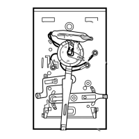
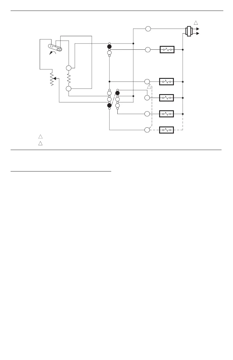
Fig. 4—Internal schematic and typical hookup diagram for single-stage heat pump systems.
M1037C
POWER SUPPLY. PROVIDE DISCONNECT MEANS AND OVERLOAD PROTECTION AS REQUIRED.
INSTALL JUMPER BETWEEN W AND Y TERMINALS WHEN HEAT RELAY IS NOT USED.
COMPRESSOR
CONTACTOR
SYSTEM
SWITCH
HEAT
OFF
COOL
FAN
SWITCH
AUTO
ON
H1
TEMP. FALL
C1
ANTICIPATOR
FAN RELAY
HEAT
OFF
COOL
C1
H1
ANTICIPATOR
G
R
Y
L1
(HOT)
L2
1
1
CHANGEOVER
RELAY (HEAT)
B
CHANGEOVER
RELAY (COOL)
O
HEAT RELAY
W
2
2
Settings and Adjustment
SYSTEM AND FAN SWITCHING
The T834C features SYSTEM and FAN switches for
control of the heating-cooling and fan systems.
The SYSTEM switch controls system operation as fol-
lows:
HEAT: Heating system only operates.
OFF: Both heating and cooling control systems are
disconnected.
COOL: Cooling system only operates.
The FAN switch controls fan operation as follows:
AUTO: For gas- or oil-fired systems, the fan operates in
response to the plenum fan control in heating; fan
operates in response to the thermostat in cooling. For
heat pump systems, the fan operates in response to
the thermostat in both heating and cooling.
ON: The fan runs continuously.
To switch positions, use thumb and index finger to slide
lever to desired position. Stop switch lever directly over
desired function indicator mark for proper circuit
operation.
TEMPERATURE SETTING
Move the temperature setting lever to the desired control
point on the temperature scale. The same lever controls the
temperature setting for either heating or cooling.
HEAT ANTICIPATOR SETTING
IMPORTANT: This thermostat has an adjustable heat
anticipator and will operate properly ONLY IF THE
ANTICIPATOR IS ADJUSTED TO MATCH THE
CURRENT DRAW OF THE PRIMARY CONTROL.
Use this thermostat only on systems with current
draws that fall within the range of the heat anticipa-
tor. Do not use this device on Powerpile (millivolt)
systems.
A current rating is usually stamped in the nameplate of
the primary control. Set the adjustable heat anticipator
indicator to match the value given on the nameplate.
If current rating is not available, proceed as follows to
determine the rating:
1. Turn off power.
2. Wire thermostat, except for connection to W termi-
nal, but do not mount it on the wall.
3. Connect ammeter between W wire and W terminal
on the thermostat (in series with the primary control).
4. Prepare the system for operation.
5. Turn on power.
6. Turn system switch to heat.
7. Increase thermostat setpoint as necessary to get sys-
tem operating.
8. With the system operating through the ammeter,
wait one minute, then read the ammeter.
9. Turn the system switch to OFF, and turn off power.
10. Adjust the heat anticipator to match the reading on
the ammeter.
11. Disconnect the ammeter, reconnect the W wire, and
mount the thermostat. Continue with system checkout.
NOTE: For best performance, the heat anticipator may
require further adjustment . To lengthen burner-on time,
move the indicator in the direction of the longer arrows,
but not more than one-half scale marking at a time. To
shorten burner-on time, move indicator in opposite di-
rection.
 Loading...