T8501 AND T8511 DELUXE ELECTRONIC THERMOSTATS
68-0162—1
13
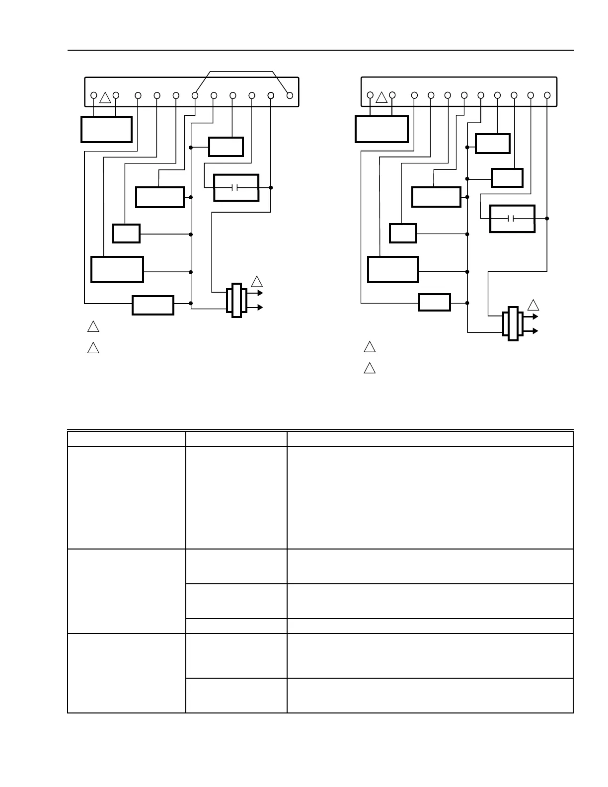
Fig. 16. Typical hookup in heat pump system with
emergency heat relay.
L1
(HOT)
L2
POWER SUPPLY. PROVIDE DISCONNECT MEANS AND
OVERLOAD PROTECTION AS REQUIRED.
AVAILABLE ON SELECT MODELS.
1
HEAT
RELAY 2
M4830
COMPRESSOR
CONTACTOR
FAN
RELAY
RO
T
O
T
O/B G Y1 C E W2
OUTDOOR
TEMPERATURE
SENSOR
COOL/HEAT
CHANGEOVER
VALVE
EM. HEAT
RELAY
THERMOSTAT
1
2
2
W1 X1
HEAT
RELAY 1
EQUIPMENT
MONITOR
Fig. 17. Typical hookup in heat pump application with
emergency heat relay and O/B terminal.
TROUBLESHOOTING GUIDE
(continued)
Symptom Possible Cause Action
Display will not come on. Thermostat is not being
powered.
• Check that C terminal is connected to the system transformer.
• Check for 24 Vac between C and R or RH terminals.
— If missing 24 Vac:
— check if the circuit breaker is tripped—reset the circuit breaker.
— check if the system fuse is blown—replace the fuse.
— check if the power switch on the HVAC equipment is in the Off
position—set to the On position.
— check wiring between thermostat and HVAC equipment—
replace any broken wires and tighten any loose connections.
— If 24 Vac is present, proceed with troubleshooting.
Temperature display is
incorrect.
Room temperature
display has been
reconfigured.
Enter Installer Setup number 37 and reconfigure the display.
Thermostat is
configured for °F or °C
display (select models).
Enter Installer Setup number 14 and reconfigure the display.
Bad thermostat location. Relocate the thermostat.
Temperature settings will
not change. (Example:
Cannot set the
heating
higher or the cooling lower.)
The upper or lower
temperature limits were
reached.
Check the temperature setpoints:
• T8511 heating limits are 40°F to 90°F (7°C to 31°C) and T8501
heating limits are 45°F to 88°F
• Cooling limits are 48°F to 99°F (9°C to 37°C).
The setpoint
temperature range
stops were configured.
Check Installer Setup numbers 34 and 35 and reconfigure the setpoint
stops.
L1
(HOT)
L2
POWER SUPPLY. PROVIDE DISCONNECT MEANS AND
OVERLOAD PROTECTION AS REQUIRED.
AVAILABLE ON SELECT MODELS.
1
AUX. HEAT
RELAY
M15092
COMPRESSOR
CONTACTOR
FAN
RELAY
RO
T
O
T
OGYCE L
OUTDOOR
TEMPERATURE
SENSOR
COOL
CHANGEOVER
VALVE
EM. HEAT
RELAY
THERMOSTAT
1
2
2
W2
EQUIPMENT
MONITOR
W1
 Loading...