EasyManua.ls Logo

Honeywell TBC2800 Series - User Manual

Honeywell TBC2800 Series
4 pages
To Next Page IconTo Next Page
Loading...
44 ซ.บรมราชชนนี 70 ถ.บรมราชชนนี ศาลาธรรมสพน์ ทวีวัฒนา กทม. 10170.
Website: https://www.add-furnace.com/ โทร: 02-888-3472
Line ID: @add11 e-mail: add028883472@gmail.com
DIGITAL BURNER CONTROLLER
TBC2800 SERIES
FEATURES
PRODUCT HANDBOOK
APPLICATION
TBC2800 series is the high-performance burner controller which is de-
signed for commercial and industrial application and suitable for gas
firing.
TBC2800 series can be used for pulse firing and modulating
firing mode.
TBC2800 series applies to multiple burners application, such as steel,
machinery manufacturing, non-ferrous metals, glass, ceramic, petro-
chemical and other industries.
INSTALLATION
TBC2800 can be installed with DIN rail or two M4 screws. While
install-ing with M4 screw, it is necessary to put the sealing gasket
beforehand so as to ensure IP 54 protection.
TBC2800 reserves 7 x M16 holes for cable wiring.
WARNING
Improper operation will cause personal injury or equipment damage!
Disconnect the power connection before installation!
Must consider the electric shock protection! Make sure the end-
users can not access the parts not proper insulated
1
Compatible to UV, Double rod (separated flame rod and
igni-tion rod) and 1 rod (integrated flame rod and ignition
rod) flame detection which can be set manually
Integrate 6 kinds of timing choices which can be set
manually according to the application requirements
24 hours continuous operation (except UV application)
Life-cycle ≥ 250K times (Note 1)
IP54 protection field or cabinet installation
Multifunctional LED lights and buttons indicate the
Flame strength, fault & operation sequence and
parameters
Remote or on-site reset
Adjustable flame on-off threshold
Comply with EN298
SPECIFICATIONS
UV sensor C7027A/C7035A/C7044A
CAUTION
Read these instructions carefully. Failure to follow them
could damage the product or cause a hazardous
condition.
Check the ratings given in the instructions and marked on
the product to make sure the product is suitable for the
application.
Installer must be a trained, experienced, flame
safeguard ser-vice technician.
After installation is completed, the operation
parameters should be set by the authorized person
according to the application requirements and this
product handbook.
Keep the flame detector cable and ignition cable as
far as possible.
C7027A/C7035A/C7044A is not the self-checking UV
sensor, so TBC2800 should be restarted once every 24
hours.
Note1: If one rod flame detection is applied, TBC2800 lifecycle will be
100,000 times.
W x D x H:
122.5 x 82 x 131.2mm
Mains input
220/230VAC 15/+10%
50 60Hz
Power consumption
Cable length of flame rod:
75m(max)
Cable length of UV 75m max)
Flame threshold setting
1~10µA
Cover
material
PC/ABS
Protection class
I
Ambient
temperature
-20
Ambient humidity
95%, non condensing
Lifecycle
250,000 cycles comply with EN298
Drive gas valve
1A(max) power factor
Drive ignition transformer 2A(max)
PF
Maximum output for terminal
2A
242Vac
Question and Answer IconNeed help?

Do you have a question about the Honeywell TBC2800 Series and is the answer not in the manual?

Honeywell TBC2800 Series Specifications

General IconGeneral
BrandHoneywell
ModelTBC2800 Series
CategoryController
LanguageEnglish

Summary

Digital Burner Controller TBC2800 Series

Product Handbook

Overview of the product's handbook content and features.

Features

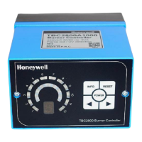
Key characteristics and capabilities of the TBC2800 series burner controller.

Application

Details on the intended uses and industries for the TBC2800 series controller.

Installation

Instructions and requirements for mounting and wiring the TBC2800 controller.

Safety Warnings and Precautions

Important safety instructions and warnings for operating and installing the controller.

Specifications

Technical details and parameters of the TBC2800 series burner controller.

Program Sequence

Normal Start-up Sequence

Describes the standard start-up procedure and timing for the burner controller.

No Flame Signal During Start-up

Details the fault lock-out procedure when no flame signal is detected.

Flame Simulation

Explains the flame simulation process during the start-up sequence.

Flame Failure Lock-out;Restart Options

Defines behavior upon flame failure: immediate lock-out or single restart attempt.

Excessive Start-up Switch-offs

Procedure for handling too frequent switch-offs during the start-up phase.

Fault Lock-out Information Summary

Fault Lock-out Information

Summary of fault conditions, results, and unlock methods for the controller.

Running State Information Summary

Details on the controller's operational states and corresponding LED codes.

Button Operation

Instructions for navigating menus and adjusting parameters using the controller's buttons.

Time Definitions

Defines various timing parameters (T1-T7) used in the burner control sequence.

LED Indicators

Explanation of the function and meaning of different LED lights and digital displays.

Dimension and Wiring Diagrams

Dimension

Physical dimensions of the TBC2800 burner controller unit.

Product Code Structure

Explanation of the product code nomenclature for the TBC2800 series.

Timing Table

Table detailing timing parameters (T2, T3) for different operational states.

Wiring Diagrams

Schematic diagrams illustrating wiring for different flame detection types.

Terminal Functions

Description of the functions for various input and output terminals.

Related product manuals