MU1H-1805GE23 R0207 4 Honeywell GmbH
GB
1. Safety Guidelines
1. Follow the installation instructions.
2. Use the appliance
• according to its intended use
• in good condition
• with due regard to safety and risk of danger.
3. Note that the appliance is exclusively for use in the
applications detailed in these installation instruc-
tions. Any other use will not be considered to comply
with requirements and would invalidate the
warranty.
4. Please take note that any assembly, commis-
sioning, servicing and adjustment work may only be
carried out by authorized persons.
5. Immediately rectify any faults which may influence
safety.
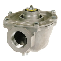
2. Functional description
As throttle valve the Alwa-Kombi-4 limits the flow
through the circulation pipe. This is achieved either by
manually closing the valve to a certain position or auto-
matically, when the valve is equipped with a thermal
actuator.
3. Technical data
4. Scope of delivery
The Alwa-Kombi-4 valve consists of:
• Valve housing in straight pattern with internal
threads to ISO 7 (DIN 2999) or external threads
according to DIN ISO 228
•Valve insert
• Handwheel with digital display of pre-setting
• Thermal actuator (accessory)
• Pipe connections (accessory)
5. Assembly
5.1 Manual adjustment of Alwa-Kombi-4 following
calculation
1. Close valve.
2. Undo bolt and remove handwheel.
3. Set the calculated value by turning the setting wheel
to the left or to the right.
4. Replace handwheel, tighten bolt and open valve.
5.2 Automatically setting the circulation tempera-
ture
1. Take the scale value from the knurling on the
temperature controlled actuator and set on the valve
as described under 5.1 (figs. 1 - 3).
2. Fit handwheel and temperature controlled actuator.
3. Tighten finger-tight to the stop
4. Open valve again.
5.3 Draining Alwa-Kombi-4 with the draining adap-
ter
1. Close valve.
2. Remove bolt.
3. CAUTION.Fit adapter in closed position. (Hexagon
is visible).
4. Fit adapter in âclosedâ position.
5. Counter hold handwheel when tightening.
6. Connect drain hose (not supplied).
7. Open drain adapter.
8. After draining, close adapter and remove.
5.4 Cleaning
6. Disposal
• Valve housing made of red bronze
• Valve insert made of red bronze and brass
• EPDM O-rings
• PTFE seat sealing
• Handwheel, pre-setting dial and display made of
plastic
Medium Water
Operating temperature max. 130 °C (266 °F)
Operating pressure max. 16 bar (232 p.s.i.)
k
vs
-value DN15
DN20
DN25
DN32 and 40
2.7
6.4
6.8
16.0
• To be carried out by an installation company
• To be carried out by the operator
Detergents must not be allowed to enter the
environment or the sewerage system!

 Loading...