J.A. Form Number 95-6996—10
Rev. 6-91 ©Honeywell Inc. 1991
Honeywell
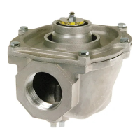
V400 AND V800
COMBINATION GAS CONTROLS
APPLICATION
V400 and V800 are used on gas fired standing pilot
appliances with 30 mV thermocouple. These gas controls
include a manual gas valve, safety shutoff, single millivolt-
age automatic operator, and pressure regulator, pilot gas
filter and flow adjustment, pressure tapping, and thermo-
couple connector.
V400 is used on 120V systems. V800 is used on 24V
systems. Refer to Table 1 for more specifications. Refer to
Table 2 for available gas capacities.
V800 gas controls are available with 1/4 x 1/4 inch or 3/
16 x 1/4 inch energy cut-off (ECO) quick-connects. With the
connector, an ECO high limit can be connected into the
power circuit. When the temperature at the ECO exceeds
the high limit, a switch opens and de-energizes the power
unit and shuts off main burner and pilot gas flow. To restart
system, pilot flame must be relit and gas control must be
reset manually.
Power for the gas control and the control system is
provided by a 30 mV thermocouple. We recommend the
Q340 Thermocouple.
Replacement parts:
1. Energy cut off (ECO) connector: 392451-1
2. Pressure Regulators:
Standard opening pressure regulator: V5306A,B.
Step opening pressure regulator: V5307A,B.
3. Valve Operators:
Line Voltage Operator: V404B.
Low Voltage Operator: V804B.
TABLE 1—MODEL SPECIFICATIONS.
MODEL NUMBER AMBIENT PRESSURE PRESSURE
SUFFIX LETTER TEMPERATURE RANGE REGULATOR TYPE REGULATOR MODEL
A32° F to 175° F Standard-Opening V5306A
[0° C to 79° C]
C32° F to 175° F Step-Opening V5307A
[0° C to 79° C]
M-40° F to 175° F Standard-Opening V5306B
[-40° C to 79° C]
P-40° F to 175° F Step-Opening V5307B
[-40° C to 79° C]
TABLE 2—GAS CONTROL CAPACITIES.
GAS CONTROL MAXIMUM MINIMUM
PIPE SIZE CAPACITY
a
AT REGULATION REGULATION
(INLET x 1 INCH WCPD CAPACITY CAPACITY
OUTLET) ft
3
/hr m
3
/hr ft
3
/hr m
3
/hr ft
3
/hr m
3
/hr
1/2" x 3/8" 110 3.1 110 3.1 11 0.3
1/2" x 1/2" 225 6.4 225 6.4 23 0.7
1/2" x 3/4" 250 7.1 290 8.2 23 0.7
3/4" x 3/4" 335 9.5 425 12.0 34 1.0
a
Capacity is based on 1000 Btu/ft
3
, 0.64 specific gravity natural gas at 1 inch wc pressure drop [37.3 MJ/m
3
, 0.64 specific
gravity natural gas at 0.25 kPa pressure drop]. Use conversion factors to convert to other gases.
TYPE OF GAS SPECIFIC GRAVITY MULTIPLY LISTED CAPACITY BY:
Manufactured 0.60 0.516
Mixed 0.70 0.765
Propane 1.53 1.62
3. Ensure installer is a trained, experienced service
technician.
4. After completing installation, use these instructions to
check product operation.
INSTALLATION
WHEN INSTALLING THIS PRODUCT…
1. Read these instructions carefully. Failure to follow
them could damage the product or cause a hazardous
condition.
2. Check the ratings given in these instructions and on
the product to ensure the product is suitable for your
application.