WIRING
Follow appliance manufacturer’s wiring instructions, if
available, or use general instructions provided below.
All wiring must comply with applicable electrical codes
and ordinances or with the National Electrical Code (ANSI/
NFPA 70), whichever applies.
Disconnect power supply before making wiring connec-
tions to prevent electrical shock.
Wiring V400 models
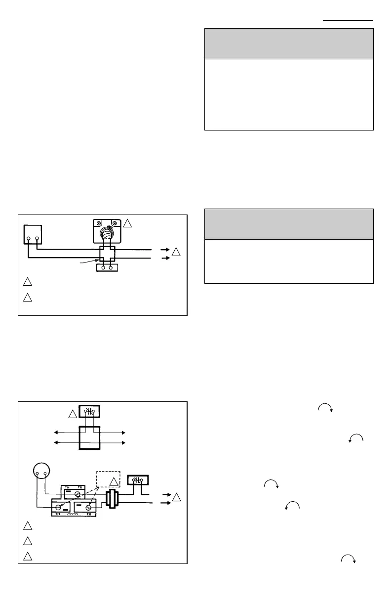
1. Refer to Fig. 5 for typical wiring diagram.
2. Ensure power supply rating on each control matches
the available supply.
3. Install line voltage thermostat (or controller) and other
controls as required.
4. Use junction box, as shown, when connecting control
circuit to gas control operator.
5. Make conduit connection to operator as follows:
a. Slip conduit fittings over integral leadwires and
screw securely into hole in operator cover.
b. Cut flexible conduit to approximate length.
c. Slip conduit over leadwires and attach to fittings.
d. Route and connect both flexible conduits to junc-
tion box.
e. Connect integral wires to control circuit. Do not
splice except within a junction box.
Fig. 5—Typical V400 wiring diagram.
Wiring V800 models
1. Ensure the power supply rating on each control
matches the available supply.
2. Install transformer, low voltage thermostat, and other
controls as required.
3. Connect control circuit to operator terminals. Refer to
Fig. 6 for a typical wiring diagram.
4. Adjust thermostat heat anticipator to 0.2A rating
stamped on valve operator.
Fig. 6—Typical V800 wiring diagram.
STARTUP AND CHECKOUT
WARNING
FIRE OR EXPLOSION HAZARD
CAN CAUSE PROPERTY DAMAGE, SEVERE IN-
JURY, OR DEATH
1. Do not force the gas control knob. Only use your
hand to push down and turn gas control knob.
Never use any tools.
2. If the gas control knob will not operate by hand, a
new control should be installed by a qualified
service technician.
GAS CONTROL KNOB SETTINGS
Gas control knob settings are as follows:
OFF prevents pilot and main burner gas flow.
PILOT permits pilot gas flow only. Gas control knob must
be held depressed or thermocouple must be heated suffi-
ciently to hold the safety control valve open.
ON permits pilot or main burner gas flow under control
of thermostat and ignition module.
PERFORM GAS LEAK TEST
WARNING
FIRE OR EXPLOSION HAZARD
CAN CAUSE PROPERTY DAMAGE, SEVERE IN-
JURY, OR DEATH
Check for gas leaks with soap and water solution any
time work is done on a gas control.
GAS LEAK TEST
1. Paint pipe connections upstream of gas control with
rich soap and water solution. Bubbles indicate gas leak.
2. If leak is detected, tighten pipe connections.
3. Stand clear while lighting main burner to prevent injury
caused from hidden leaks which could cause flashback in
the appliance vestibule. Light main burner.
4. With main burner in operation, paint pipe joints (in-
cluding adapters) and control inlet and outlet with rich soap
and water solution.
5. If another leak is detected, tighten adapter screws,
joints, and pipe connections.
6. Replace part if leak can not be stopped.
LIGHT PILOT
1. Turn gas control knob clockwise to OFF. Wait
five minutes to dissipate any unburned gas. Sniff around the
appliance near the floor. Do not relight pilot flame if you
smell gas.
2. Turn gas control knob counterclockwise to
PILOT. Push down and hold the knob while lighting the pilot
flame.
3. Hold the gas control knob down about one minute,
then release.
• If pilot flame goes out, turn gas control knob
clockwise to OFF and repeat steps 1
through 3.
• If pilot flame remains lit, turn gas control knob
counterclockwise to ON.
ADJUST PILOT FLAME
The pilot flame should envelop 3/8 to 1/2 in. [10 to 13
mm] of the thermocouple tip. Refer to Fig. 7. To adjust pilot
flame:
1. Remove pilot adjustment cover screw. Refer to Fig. 3.
2. Turn inner adjustment screws clockwise to de-
4
M17846
L2
LINE VOLTAGE
OPERATOR
LINE VOLTAGE
THERMOSTAT
OR CONTROLLER
L1
(HOT)
1
1
2
2
JUNCTION BOX
POWER SUPPLY. PROVIDE DISCONNECT MEANS AND
OVERLOAD PROTECTION AS REQUIRED.
LINE VOLTAGE ENCLOSURE NOT PART OF GAS CONTROL.
LINE VOLTAGE GAS CONTROLS MUST BE USED IN AN
OEM APPROVED ENCLOSURE.
LIMIT
CONTROLLER
1
1
2
3
POWER SUPPLY. PROVIDE DISCONNECT MEANS AND OVERLOAD
PROTECTION AS REQUIRED.
NEVER JUMPER THESE TERMINALS. THIS SHORTS OUT VALVE COIL
AND MAY BURN OUT HEAT ANTICIPATOR IN THERMOSTAT.
ORDER ECO LIMIT AND LEADWIRES SEPARATELY.
3
2
ECO
CONNECTOR
POWER
UNIT
24 VOLT
THERMOSTAT
ECO LIMIT
THERMOCOUPLE
CAUTION
HIGH LIMIT
CONTROLLER
–SEE
L1
(HOT)
L2
TRANSFORMER
M17848

 Loading...