3 60-2309—8
V4055A,B,D,E
SPECIFICATIONS
ELECTRICAL RATINGS: V4055A,D:
-40°F to 20°F [-40°C to -7°C] 20°F to 150°F [-7°C to 66°C]
V4055 Model lb N lb N
Without return spring 5 22.2 20 89.0
With return spring 5 22.2 10 44.5
APPROVALS:
Underwriters Laboratories Inc. Listed: File No. MH1639,
Guide No. YIOZ.
Factory Mutual Approved.
International Approval Services (IAS, a joint venture of
AGA and CGA): 60 Hz only.
British Gas Corporation and Dutch Gas Institute Ap-
proved:
V4055 with several V5055A and V5055B models.
V4055D with V5055C models with an internal screen.
ACCESSORIES:
133533A Short Stem Adapter for mounting actuator on
V5034 valve.
133534A Long Stem Adapter for mounting actuator on
V5034 valve.
133568 Auxiliary Switch Bag Assembly.
133569 Valve-Closed Indication Switch Bag Assembly
(do not use with V5034 valve body).
7616BR Damper Crank Arm (damper arm and clip).
Q5055A1001 Adapter Assembly: Adapts ITT General
V710 Gas Valve to accept Honeywell gas valve
actuators. Replaces ITT General AH2 gas valve
actuators.
AVAILABLE MODELS:
V4055 with NEMA 4 enclosure (weatherproof).
a
50 Hz power supply.
b
60 Hz power supply.
V4055B,E–120V, 60 Hz.
Opening—60W 0.94A (5.4A inrush), 115 VA.
Holding—9.5W, 0.16A, 19 VA.
AUXILIARY SWITCH AND PROOF-OF-CLOSURE
SWITCH RATINGS: 1/2 hp [0.37 kW]
a
:
Load 120V 240V
Full Load 9.8A 4.9A
Locked Rotor 58.8A 29.4A
a
Maximum total connected power to both switches (if used)
is 1800 VA.
MOUNTING DIMENSIONS: See Fig. 1.
DAMPER SHAFT: Models available with or without inte-
gral damper shaft. Shaft is 3/8 in. [9.5 mm] square, for use
with 7616 BR Damper Crank Arm (not included). Mod-
els available with or without damper shaft return spring.
MAXIMUM DAMPER SHAFT ROTATION: 52 angular
degrees.
DAMPER SHAFT MAXIMUM FORCE A 2-11/16 in.
[68.3 mm] RADIUS FOR 7616 BR DAMPER CRANK
ARM (ordered separately):
NOTE: Damper shaft drives damper crank arm in one direc-
tion only; optional return spring is available on damper
shaft to turn damper crank arm in opposite direction.
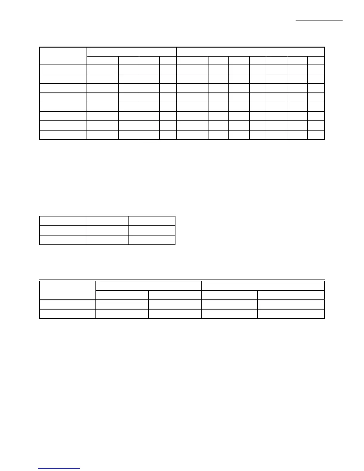
Voltage and Opening (Standard) Opening (Fast) Holding
Frequency Inrush W A VA Inrush W A VA W A VA
100/50-60
a
– 43.0 0.91 91 – 58.0 1.30 130 10.4 0.16 16
100/50-60
b
– 33.0 0.67 67 – 43.0 0.91 91 8.4 0.14 14
120/60 3.9 50.0 0.94 115 5.4 71.0 1.33 160 9.5 0.12 14
200/50-60
a
– 68.0 0.79 158 – 88.0 1.10 220 10.6 0.09 18
200/50-60
b
– 48.0 0.52 104 – 63.0 0.72 144 9.0 0.07 14
220/50 1.6 55.5 0.55 121 3.0 76.0 0.80 176 9.0 0.06 14
240/50 – 81.5 0.79 190 – 95.0 1.00 240 9.1 0.06 14
240/60 2.6 51.0 0.45 115 4.0 71.5 0.68 160 9.2 0.06 14

 Loading...