60-2309—8 4
V4055A,B,D,E
INSTALLATION
B
E
F
C
D
A
3
1
D
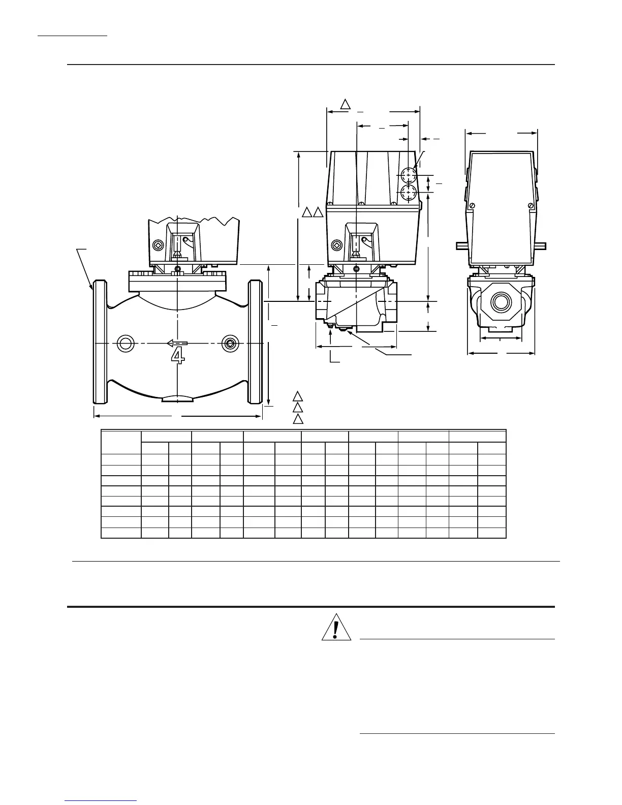
1/4 INCH NPT
DOWNSTREAM TAP
AND PLUG
1/4 INCH NPT
UPSTREAM TAP
AND PLUG (1/4 BSP
ON INTERNATIONAL
MODELS)
1
2
3
[32.5]
KNOCKOUT
FOR1/2 INCH
CONDUIT (4)
OCTAGON
3/4 (19.1) BOLT
HOLES (8)
ON 3-3/4 [95.3]
RADIUS
1
9
32
9
3
16
[233.4]
27
32
[21.4]
3
23
32
5 [127.0]
[94.5]
2
6
3
4
[171.5]
ALLOW 4 IN. [101.6 MM] CLEARANCE FOR ACTUATOR REMOVAL.
ADD 1/8 IN. [13.2 MM] TO DIMENSION FOR MODELS WITH NEMA 4 ENCLOSURE.
ADD 1/4 IN. [6.4MM] TO DIMENSION A FOR MODELS WITH NEMA 4 ENCLOSURE.
M7332
3/4
1
1-1/4
1-1/2
2
2-1/2
3
4
VALVE SIZE
INCH
11-1/8
11-1/8
11-1/8
11-1/8
11-1/4
11-3/4
11-3/4
14-1/8
282.6
282.6
282.6
282.6
285.8
298.5
298.5
358.8
2-3/4
2-3/4
2-3/4
2-3/4
2-7/8
3-3/8
3-3/8
5-13/16
69.9
69.9
69.9
69.9
73.0
85.7
85.7
147.6
8-3/16
8-3/16
8-3/16
8-3/16
8-5/16
8-13/16
8-13/16
11-7/32
208.0
208.0
208.0
208.0
211.1
223.8
223.8
285.0
5-3/4
5-3/4
5-3/4
5-3/4
8-3/8
9-1/4
9-1/4
12-1/2
146.1
146.1
146.1
146.1
212.7
235.0
235.0
317.5
2-1/4
2-1/4
2-1/4
2-1/4
2-3/4
2-3/4
2-3/4
4-5/8
57.2
57.2
57.2
57.2
69.9
69.9
69.9
117.5
4-13/16
4-13/16
4-13/16
4-13/16
7-19/32
7-19/32
7-19/32
—
122.2
122.2
122.2
122.2
192.9
192.9
192.9
—
2-13/16
2-13/16
2-13/16
2-13/16
3-1/2
4-1/2
4-1/2
—
71.4
71.4
71.4
71.4
88.9
114.3
114.3
—
DIM A
IN. MM
DIM B
IN. MM
DIM C
IN. MM
DIM D
IN. MM
DIM E
IN. MM
DIM F
IN. MM
OCTAGON
IN. MM
Fig. 1—Approximate Mounting Dimensions of V4055 Actuators and V5055 Valves, in in. [mm].
Installation
CAUTION
1. Disconnect power supply before making wiring
connections to prevent electrical shock and
equipment damage.
2. Voltage and frequency of the power supply
connected to this control must agree with those
marked on the device.
3. Maximum total connected load to both switches
(if used) must not exceed 1800 VA.
WHEN INSTALLING THIS PRODUCT . . .
1. Read these instructions carefully. Failure to follow
them could damage the product or cause a hazardous
condition.
2. Check the ratings given in the instructions and on the
product to make sure the product is suitable for your
application.
3. Installer must be a trained, experienced, flame safe-
guard control technician.
4. After installation is complete, check out product op-
eration as provided in these instructions.

 Loading...