11 60-2080—8
V48A,F,J; V88A,J
SERVICE INFORMATION
17. Replace the housing cover, and tighten the cover
screw holding it to the actuator housing (Fig. 12).
18. Close the master switch.
19. Test the valve to make sure it opens and closes as
described in the Operation section.
20. Verify proper operation after servicing.
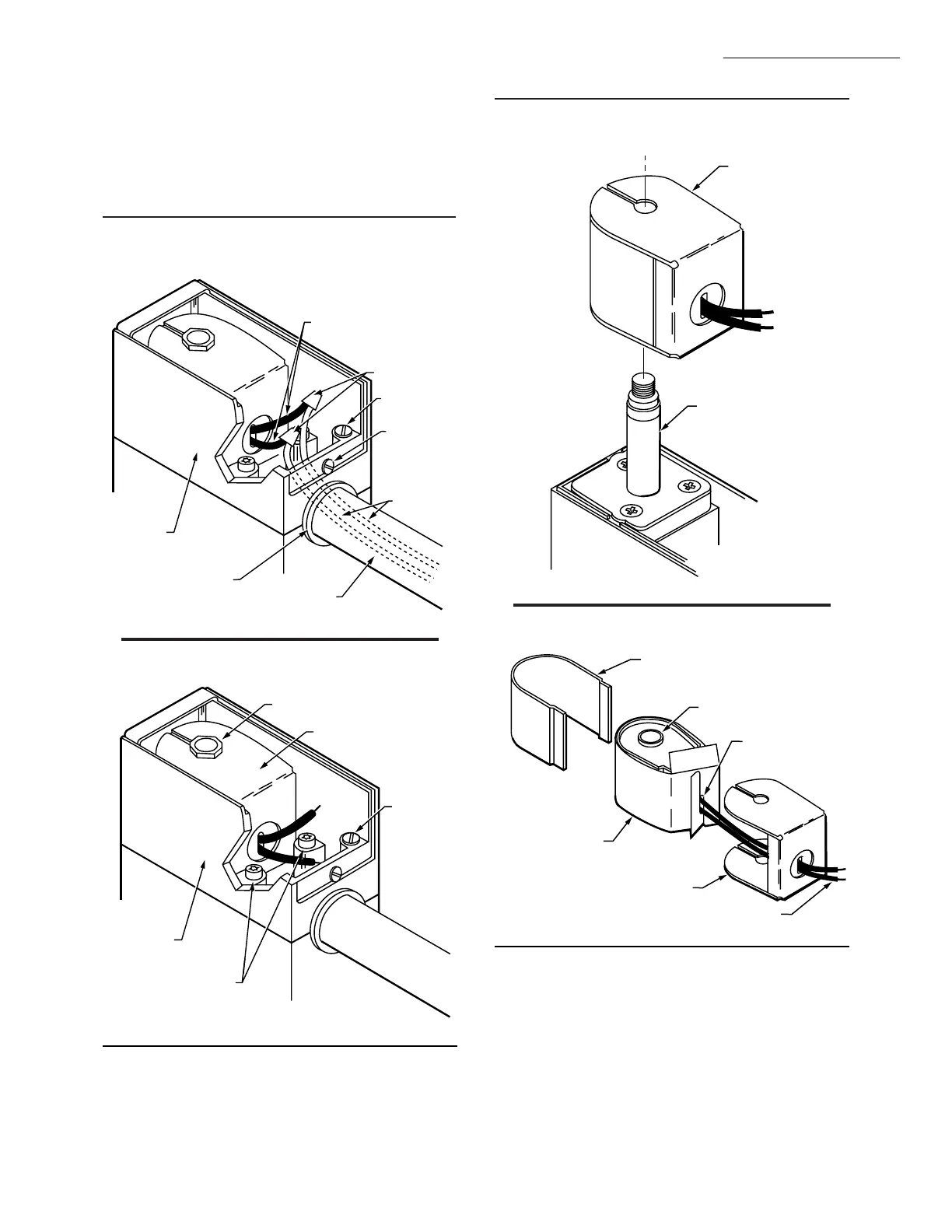
Fig. 12—Wiring connections and actuator
housing
M7302
6 IN. [152.4 MM] INTERNAL
BLACK LEADWIRES
(FROM COIL)
SOLDERLESS
CONNECTORS
GROUNDING
SCREW
EXTERNAL
WIRES
ACTUATOR
HOUSING
OPENING IN
ACTUATOR
HOUSING
CONDUIT
(IF REQUIRED)
COVER
SCREW
Fig. 13—Internal view of actuator housing.
M7301
HOLDING NUT
COIL ASSEMBLY
GROUNDING
SCREW
2 TORX 20
SCREWS HOLDING
ACTUATOR HOUSING
ACTUATOR
HOUSING
Fig. 14—Coil assembly fits on plunger tube
assembly
COIL ASSEMBLY
PLUNGER TUBE
ASSEMBLY
M7303
Fig. 15—Coil assembly, insulator, and cover.
WRAPAROUND
METAL COVER
M7304
BLACK LEADWIRES
METAL BASE
CARDBOARD
INSULATOR
COIL
ASSEMBLY
CARDBOARD
INSULATOR
HOOKED TOGETHER
 Loading...


