EasyManua.ls Logo

Honeywell VERSAFLOW VORTEX 200 User Manual

Honeywell VERSAFLOW VORTEX 200
4 pages
To Next Page IconTo Next Page
Page #1 background imageLoading...
Page #1 background image
Quick Start
For initial set up, we strongly recommend the use of the relevant manuals in addition!
07/2019 - 4007779101 - 34-VF-25-76 iss.1 GLO July 2019 US
1
VERSAFLOW VORTEX 200
Vortex flowmeter
Installation, assembly, start-up and maintenance may only be performed by appropriately
trained personnel.
For use in hazardous areas, special codes and regulations are applicable which are supplied in
a separate document that describes all hazardous area relevant information.
The responsibility as to the suitability, intended use and corrosion resistance of the used
materials against the measured fluid of this device rests solely with the operator.
For complete documentation (manuals, supplementary manuals, data sheets and certificates)
please refer to www.honeywellprocess.com.
1 Installation
Liquids
Steam & gases
Sandwich design – centering rings
Centering rings
(part of scope of supply)
Transport
Pipelines with control valve
Remote: wall mounting of the field housing
Remote: pipe mounting of the field housing
5 DN

Other manuals for Honeywell VERSAFLOW VORTEX 200

Question and Answer IconNeed help?

Do you have a question about the Honeywell VERSAFLOW VORTEX 200 and is the answer not in the manual?

Honeywell VERSAFLOW VORTEX 200 Specifications

General IconGeneral
BrandHoneywell
ModelVERSAFLOW VORTEX 200
CategoryMeasuring Instruments
LanguageEnglish

Summary

Installation

Transport

Process of transporting the flowmeter.

Sandwich design and centering rings

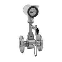
Details the sandwich design and associated centering rings.

Remote mounting options

Covers wall and pipe mounting for the field housing.

Pipelines with control valve

Illustrates pipeline configurations including a control valve.

Electrical Connection

Connecting the Signal Converter

Instructions for connecting the signal converter, including terminal details.

Minimum Inlet and Outlet Sections

Specifies required upstream and downstream pipe lengths.

Heat Insulation and Sunshade

Guidelines for heat insulation and sunshade installation.

Signal Outputs and Inputs

Current Output

Details on connecting the 4-20 mA current loop.

Current Input

Connection for power supply and external transmitters.

Pulse/Frequency Output

Configuration for pulse or frequency signal output.

Limit Switch and Status Output

Wiring for limit switch and status signals.

Quick Setup and Configuration

Menu Navigation and Setup Options

Overview of menu structure for quick setup.

Access Levels and Permissions

Details user, operator, and expert access levels and permissions.

Contact Information

Honeywell Process Solutions contact details and website.

Related product manuals