Do you have a question about the Honeywell H Series and is the answer not in the manual?
Checks meter's input voltage rating against service feeds for compatibility.
Confirms current sensors are correctly sized for the monitored load based on color codes.
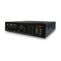
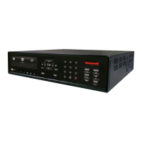
Describes the unit's composition of main power and display boards.
Details connections for MAIN Power Input and current sensors on terminal blocks.
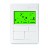
Explains the display board's connection and its role in showing metered values and errors.
Describes the input board for third-party meter pulses and its communication via protocols.
Explains the format for defining brand, class, voltage, sensors, and enclosure for ordering.
Details input voltage, power, current ratings, and power factor.
Covers temp, humidity, altitude, pollution, installation, display, and ranges.
Details RS-485 serial comms specs and battery cell information.
Explains FCC compliance for Class B digital devices and measures to correct interference.
Describes cautionary and electrical shock hazard labels, advising manual consultation and power disconnection.
Warns about electrostatic discharge sensitivity of circuit components and how to prevent it.
Alerts to high voltages on terminals and the need for qualified personnel and code compliance.
Highlights enclosure grounding risks and prohibits panel opening with power applied.
Provides enclosure dimensions and notes for mounting the meter enclosure.
Details steps for ESD protection grounding and installing the protective earth ground.
Describes wire entry, MAINS wiring, neutral handling, and external fuse installation.
Details connecting AC power wires and lists the initial meter display screens.
Guides voltage verification and explains line voltage phasing importance and error messages.
Guides on connecting current sensors to TB1 terminals and describes sensor types.
Details how to open, reassemble, and orient the split-core sensor around conductors.
Explains connecting sensor wires, error messages, and diagnostic programs.
Describes the BEAT, STATUS, and LOAD LEDs and their indications.
Illustrates wiring diagrams for three-phase and single-phase installations.
Explains diagnostic messages for line voltage faults like "PH Missing" or "Phase sequence error".
Details how current sensor diagnostics detect issues like reversed sensors or incorrect phase correspondence.
Describes the daisy-chain method for connecting multiple meters via RS-485.
Illustrates the RS-485 terminal on the main power board and connections for daisy-chaining.
Explains connecting a PC via RS-232 key to the RS-485 network for communication.
Details using the RS-232 communication key to connect meters to a PC with E-Mon Energy software.
Provides steps for connecting the RS-232 key to the computer using cables and adapters.
Explains connecting meters to the RS-232 key via RS-485 using a modular plug method.
Describes connecting the RS-232 key to an external modem for remote communication.
Details how to select and configure the communication baud rate using jumpers for EZ-7 protocol.
Explains how the USB Key provides a termination point for RS485 wiring from meters.
Describes connecting the meter to a network via the RJ-45 Ethernet port and its LEDs.
Outlines rules for accurate readings when using parallel current sensors for multiple loads.
Illustrates the wiring diagram for three-phase multiple-load monitoring.
States that the unit is factory-calibrated and requires no internal adjustments or scheduled maintenance.
Lists battery specifications and warns against using incorrect types and reiterates ESD precautions.
Shows the battery cell location and provides step-by-step instructions for its replacement.
Identifies the four push buttons on the display board and their general configuration uses.
Explains how to navigate menus to set Date/Time, Device ID, IP, and BACnet settings.
Details how to reset peak kW demand and/or kWh using the display board buttons.
Describes how to lock the meter's display on a specific screen for a set duration.
Provides an overview of the nine scrolling display screens and their general content.
Explains the first three display screens showing energy, cost, and CO2 metrics.
Details displays for peak demand, actual load, phase current, voltage, and power factor.
Addresses questions about voltage tapping, conduit routing, and wire sizing.
Answers questions on monitoring parallel feeds, different subpanels, and multiple breakers.
Lists Modbus registers for energy, power, factor, current, voltage, and external inputs.
Describes BACnet object descriptors for energy delivered/received and real, reactive, apparent power.
Details BACnet object descriptors for power factor, current, voltage, and phase angle.
Lists BACnet object descriptors for frequency, phase angle, and reserved inputs.
Maps Lonworks SNVT types for energy delivered/received and real, reactive, apparent power.
Maps Lonworks SNVT types for power factor, current, and voltage measurements.
Lists exclusions, labor costs, and liability limitations for the meter's warranty.
| Brand | Honeywell |
|---|---|
| Model | H Series |
| Category | Measuring Instruments |
| Language | English |