H-SERIES GREEN CLASS NET METER
62-0424-02 6
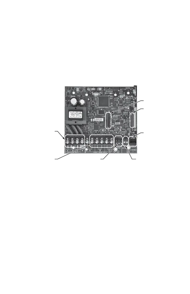
2.1 Main Power Board
Connections to this board include the MAIN Power Input and current sensors. The
MAIN Power Input terminals are positions one through four on the four position screw
terminal block, TB1. These terminals are covered with a protective shield for safety
purposes. The current sensor assemblies interface to the TB2, TB3 and TB4. Each
terminal block corresponds to an input voltage phase; care must be exercised to
ensure that each current sensor is connected to the correct terminal block. One three
terminal screw connector(TB42) is provided for RS-485 communications. One RJ-45
jack (J8) is provided for 10/100-base T Ethernet. One two terminal screw connector
provides phase loss alarming.
Fig. 2. Main Power Board Connections.
M33271
J3
J4
TB1
POSITIONS 1-4
MAIN POWER INPUT
TB1 POSITIONS 6-10
CURRENT SENSOR
INPUTS
ETHERNET
CONNECTION
RS-485
CONNECTION
PHASE OUTPUT

 Loading...