H-SERIES GREEN CLASS NET METER
19 62-0424-02
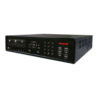
6.4.1 Installing the Split-Core Current Sensor Assembly
1. Each phase being monitored will require one two-piece current sensor assembly.
Open the two-piece current sensor assembly by releasing the nylon clamp using
a fl at head screwdriver.
Fig. 7. Split Core Current Sensor.
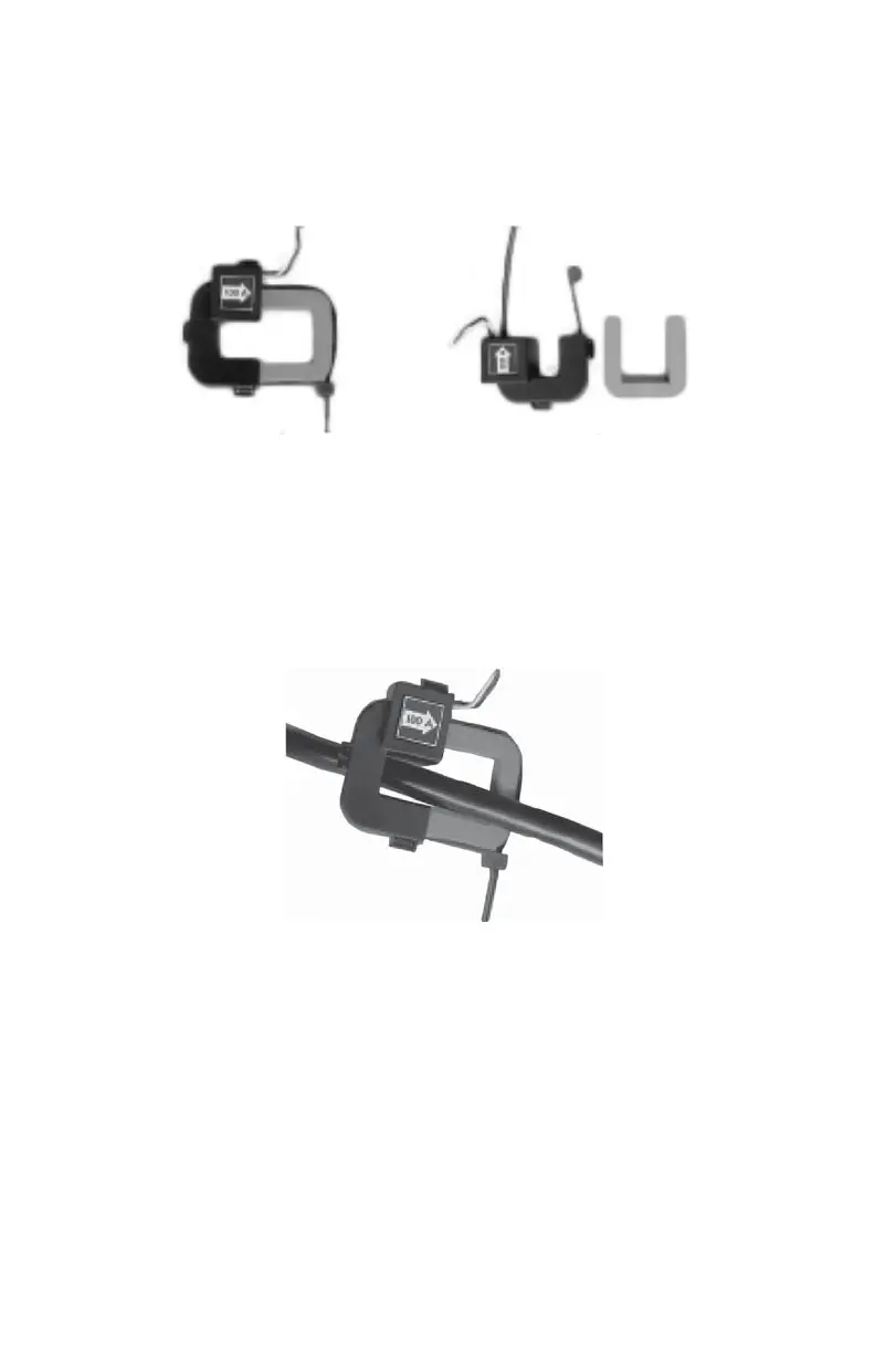
2. Reassemble the current sensor assembly around the conductor(s) to be moni-
tored. Ensure the current sensor halves marked “Load” are both facing the load
side of the conductor. The colored arrow will be on the source side of the con-
ductor being monitored and MUST be pointed in a clockwise direction around
the conductor being monitored. Tighten the nylon clamp to complete the assem-
bly.
Fig. 8. Install On a Split Core Sensor.
IMPORTANT:
When looking from the source side of the conductor(s) being monitored, you should
see the arrow on the current sensor assembly. The arrow should be pointing in a
clockwise direction around the conductor(s) being monitored. If the arrow is not
positioned on the source side, inaccurate readings will result.

 Loading...