2 Installation Instructions Viewguard DUAL / AM FAI
1. Introduction
2. Installation Guide line
3. Installation
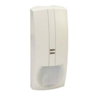
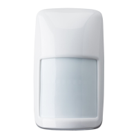
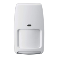
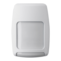
The Viewguard DUAL motion detector comprises two systems that operate fully
independently: Passive infrared detector plus Microwave detector. The functioning principle
of the detector is based on the intelligent linkage of a passive infrared sensor and
microwave. This type of linking renders the detectors particularly insensitive to air and
thermal turbulences. (Microwave module see Fig. ).
They are delivered with the following main features:
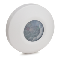
Volumetric mirror optic
, see Fig. , (only 033440/450)
FAI (First Alarm Indication):
Selectable range and sensitivity
Memory function
Selectable range and sensitivity
Self-test (only 033440 )
Monitoring of operating voltage
Tamper and back tamper
Maximum sensitivity is achieved when mounted crosswise to the horizontal detection
zones of the PIR sensors. Therefore, select a mounting site that runs crosswise to the
expected direction of motion. (See Fig. ).
Minimum distance to ceiling: 2 cm
* Mounting above radiators
* Mounting near air discharge openings (e.g. air conditioning systems)
* Direct sunlight
* Mounting near to fluorescent lamps
* Mounting near to light bulbs
(see Fig. 1)
If necessary, break the seal with a small screwdriver or similar object and pull downward
. Press the notch (at the bottom in the middle, see Fig. ) slightly inward and
press off the front of the housing . Lift off the housing front .
• 0° Vertical see Fig. 5/1 Fig.
• Vertical at a 3° downward angle see 5/2 Fig.
• Horizontal at a 45° angle to the left or right see 5/3 Fig.
• Corner mounting see 5/4 Fig.
The detector can be mounted by using the optional swivel bracket (033390 or 033588, see
"Accessories").
(See 4)
For surface mounted wiring
For flush mounted wiring
For use with adjusting hinge
For strain relief with cable strap
3-
(see Fig. 3- , Fig. 6)
2-
Microwave sensor inactive in the "disarmed" state.
When multiple detector on a single zone, Indicate the first detector in alarm
/450
6-A
2-
4-
Fig. 4-
Fig. 4-
Fig. 4-
Fig.
(see Fig. 4)
Required for installation according to DIN CLC/TS 50131-2-4 grade 3.
The backtamper can be used if installed as illustrated in Fig. 5/1, 5/2, 5/3a, 5/3b and 5/4.
Tappet for backtamper. Remove the pin at the tappet, if the backtamper is
being used (see illustration)
Protective cover for back-tamper (on the rear). Remove, when mounting as
per Fig. 5/3a or 5/4
-
-
-
-
-
-
-
-
-
Avoid:
Open housing
Mounting options Screw on position
Cabling, strain relief
A
B, C
C
D
Anti-masking up to 30 cm from the detector
-
Backtamper
a
b
4.2 Easy Logic operating mode without FAI function
The control signals "Walk test", "disarmed" and "FAI" are not connected. In this operating
mode no alarm indication, no FAI function and no memory is available.
The DIP-switches S4, S5 and S6 must be in position "ON".
The Microwave sensor is always active.
Detector 1
F
Detector 2 Detector 3
Detector 20
F
F
F
Function of inputs:
(Pull-up resistors in the detector)
Function
a) armed
b) disarmed
c) walk test, clear alarm indication
High
Low
Inputs
walk test "T" arm/disarm "U"
High
High
Low
Low
4.1 Viewguard operating mode with FAI function
(FAI = irst larm ndication)
The FAI connections "F" of all detectors are connected to one another. A connection to the
control panel is not required. The LED flashes on the detector that triggers first, the LED
light on the subsequently triggered detectors (see 6. "LED indication").
FA I
FAI logic:
Close housing
Apply operating voltage
Walk test in Easy Logic mode
See Fig. 1 in reverse order. Ensure that the housing is closed correctly and locked into
position. Do not insert the seal to lock the housing until installation is completed
After applying the operating voltage, the detector automatically performs an initialisation.
Both LEDs flash (see 6.). . After max.
60 seconds the detector is ready for operation. After this period, do not change anything in
the close vicinity (up to 50 cm) that may influence the reflected light.
The detector is automatically in for approx. after initialising is
completed. Conduct the walk test within this time period. LED indication see 6.
The detector is operationally ready after the 10 minutes have expired.
Do not enter the Anti-Mask range during initialisation
walk test mode 10 minutes
5. Setting
DIP-switches: see Fig. 3-
S3 Sensitivity
ON normal
OFF high
S1 S2 Range
OFF OFF 8 m
ON OFF 11 m
OFF ON 13 m
ON ON 15 m
S4 S6 Operating mode ()Anti-Mask only 033440/
ON ON Easy Logic mode only (see 4.2)
ON OFF Viewguard mode with FAI
OFF OFF Viewguard mode with FAI
OFF ON
450
Anti-Mask always active
Anti-Mask always active
Anti-Mask inactive in "armed" state
N.A.
S5 Fault/Cover
ON do not save
OFF save
Memory:
Do not save:
Save:
Fault/cover signal is automatically cleared after
elimination of the fault/cover.
Not possible in Easy Logic mode!
Fault/cover signal remains saved in the detector
until it is cleared via control panel.
4. Connection diagram
Installation Instructions
Viewguard Series DUAL
GB
Fault Tamper Alarm T U F
-
+
Fault
Alarm
Tamper
Walk test
0V
+12VDC
Spare terminals for
end of line resistors
arm/disarm
FAI
Fault Tamper Alarm
If the control panel has no fault input,
the "Alarm" and "Fault" outputs can
beconnectedinseries.
PIR and MW operate automatically
with the same range.

 Loading...