VPI PRESSURE INDEPENDENT CONTROL VALVES & ACTUATORS
19 31-00383-01
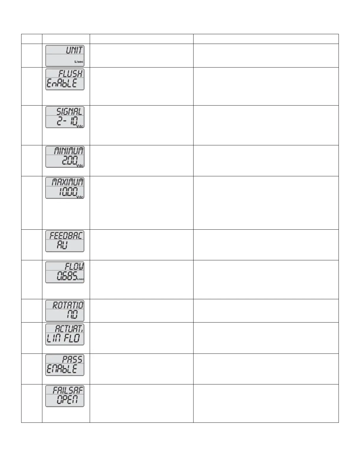
Choose unit scale for flow rate.
*scrolling top: SELECT UNIT SCALE
Default: l/sec.
Options: l/sec or l/hr or GPM
Activate Flush mode at start-up
*scrolling top: SELECT FLUSH MODE
Default: Enable.
Options: Enable or Disable.
When no control signal (analog) is detected at start
up, flush mode is started (5/6 of fully opened). It
will be dismissed when control signal is detected.
Select type of control signal
*scrolling top:
SELECT CONTROL SIGNAL
Default: 2-10VDC.
Options: 2-10VDC or 4-20mA or digital. Choose:
• 2-10VDC for VDC
• 4-20mA for mA
• Digital for 2 position or 3-point floating.
Select minimum control value
*scrolling top: SET MINIMUM LIMIT
Volt default: 2.
Options: from 0-7. Increment: 0.1. mA default: 4.
Options: from 0-14. Increment: 0.2. NA if Digital (in
step 5).
Select maximum control value
*scrolling top: SET MAXIMUM LIMIT
Volt default: 10.
Options: from 3-10 and at least 3 VDC greater than
the selected minimum limit. Increment: 0.1.
mA default: 20.
Options: from 6-20 and at least 6 mA greater than
the selected minimum limit. Increment: 0.2.
NA if Digital (in step 5).
select feedback signal
*scrolling top:
SELECT FEEDBACK SIGNAL
Default: AU; Automatic match of control signal if
analog.
Options: 0-10 VDC, 2-10 VDC or 4-20 mA or AU.
If Digital (in step 5) AU is not an option.
Set the designed maximum flow.
Accuracy: Greatest of either ±5% of
de-signed max. flow or ±2% of max.
valve flow.
*scrolling top: SELECT MAXIMUM FLOW
Default: Maximum setting.
Values depend on valve model and unit scale
chosen in step 2 and 3.
Stepping increments as per tech note
Select direction of rotation.
*scrolling top: SELECT ROTAT DIRECT
Default: Normally Closed (NC).
Options: Normally Open (NO) or Normally Closed
(NC).
Select actuator mode.
*scrolling top: ACTUATOR MODE
Default: Linear flow.
Options: Linear flow, Equal percentage, Linear
rotation or Linear signal.
Activation of password.
*scrolling top: ACTIVAT PASSWORD
Default: Disable.
Options: Enable or Disable.
If Enabled password is required to access alarm
and programming menu.
Select direction of rotation when
Failsafe.
*scrolling top:
SELECT FAIL SAFE DIRECT
Default: Closed.
Options: Open or Closed.
Only valid for SM.0.0.0.4 (failsafe model). Failsafe
direction open means opening to max. flow chosen
in step 9.
 Loading...