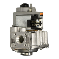
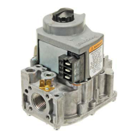
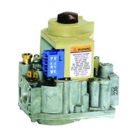
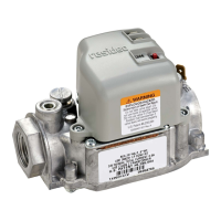
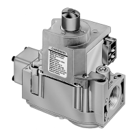
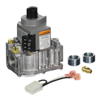
VR8200, VR4200
SPECIFICATIONS
3 68-0046—4
TABLE 2—GAS CAPACITY
CONVERSION FACTORS.
Specific Multiply Listed
Gas Gravity Capacity by
Manufactured 0.60 0.516
Mixed 0.70 0.765
Propane 1.53 1.62
BODY PATTERN: Straight-through with 1/2 inch inlet and
1/2 inch outlet. Flanges available for 3/8, 1/2 and 3/4 inch
straight and 90° angle connection. See Table 3.
TABLE 1—MODEL SPECIFICATIONS.
Model No. Opening Type Standard Factory Optional Factory Range of Field
Suffix Charac- of Settings Regulator Settings Adjustment
Letter teristic Gas in. wc kPa in. wc kPa in. wc kPa
VR8200A, M Standard- Natural 3.5 0.9 3 to 5 0.7 to 1.2 3 to 5 0.7 to 1.2
VR4200A, M opening LP 10.0 2.5 8 to 12 2 to 3 8 to 12 2 to 3
VR8200C, P Step- Natural Step—0.7, Step—0.17, Step—0.7, Step—0.17, Step—none; Step—none;
VR4200C, P opening 0.9, 1.2 or 0.22, 0.30 or 0.9, 1.2 or 0.22, 0.30 or Full Rate— Full Rate—
1.7, as 0.48 as 1.7, as 0.48 as 3-5 0.7 to 1.2
ordered
a
ordered
a
ordered
a
ordered
a
Full Rate— Full Rate— Full Rate— Full Rate—
3.5 0.9 3 to 5 0.7 to 1.2
LP Step—1.4, Step—0.35, Step—1.4, Step—0.35, Step—none; Step—none;
2.5, 4.0 or 0.62, 0.99 or 2.5, 4.0 or 0.62, 0.99 or Full Rate— Full Rate—
5.5, as 1.37, as 5.5, as 1.37, as 8-12 2 to 3
ordered
a
ordered
a
ordered
a
ordered
a
Full Rate— Full Rate— Full Rate— Full Rate—
10 2.5 8 to 12 2 to 3
VR8200H Slow- Natural 3.5 0.9 3 to 5 0.7 to 1.2 3 to 5 0.7 to 1.2
VR4200H opening LP 10.0 2.5 8 to 12 2 to 3 8 to 12 2 to 3
VR8200J Delayed and Natural 3.5 0.9 3 to 5 0.7 to 1.2 3 to 5 0.7 to 1.2
Slow-opening LP 10.0 2.5 8 to 12 2 to 3 8 to 12 2 to 3
a
Step pressure not adjustable.
Fig. 1—VR8200, VR4200 dimensions in in. [mm].
NOTE: Flange Kits include one flange with attached O-ring
and four mounting screws. TRADELINE kits include
9/64 in. hex wrench, as noted.
PILOT GAS OUTLET: Compression fitting for 1/4 in. OD
tubing.
TABLE 3—FLANGE PART NUMBERS.
Part Number
Inlet/Outlet Flange Less Hex With Hex
Pipe Size Type Wrench Wrench
3/8 in. NPT Straight 393690-1 393690-11
Elbow
a
393690-2 393690-12
1/2 in. NPT Straight 393690-6 393690-16
Elbow
a
393690-3 393690-13
3/4 in. NPT Straight 393690-4 393690-14
Elbow
a
393690-5 393690-15
a
Elbow (angle) flanges cannot provide right hand inlet
when the ECO connector is used.
M9059
3
[89]
1
2
1
[43]
11
16
11
16
2 [69]
1 [25]
1
2
[13]
1
8
4 [104]
3-5/8 [91]
SWING
RADIUS
CONVENIENCE TERMINALS
CONDUIT
COVER
VR4200
3
[89]
1
2
1
[43]
11
16
11
16
2 [69]
1
4
3 [83]
1 [25]
1
2
[13]
1
8
4 [104]
3-5/8 [91]
SWING
RADIUS
1/4 INCH QUICK-CONNECT
TERMINALS
CONVENIENCE TERMINALS
VR8200
1 SCREW TERMINALS ON
TRADELINE MODELS ONLY.
1

 Loading...
