T8635L MICROELECTRONIC COMMUNICATING PROGRAMMABLE THERMOSTAT
69-1331—5 16
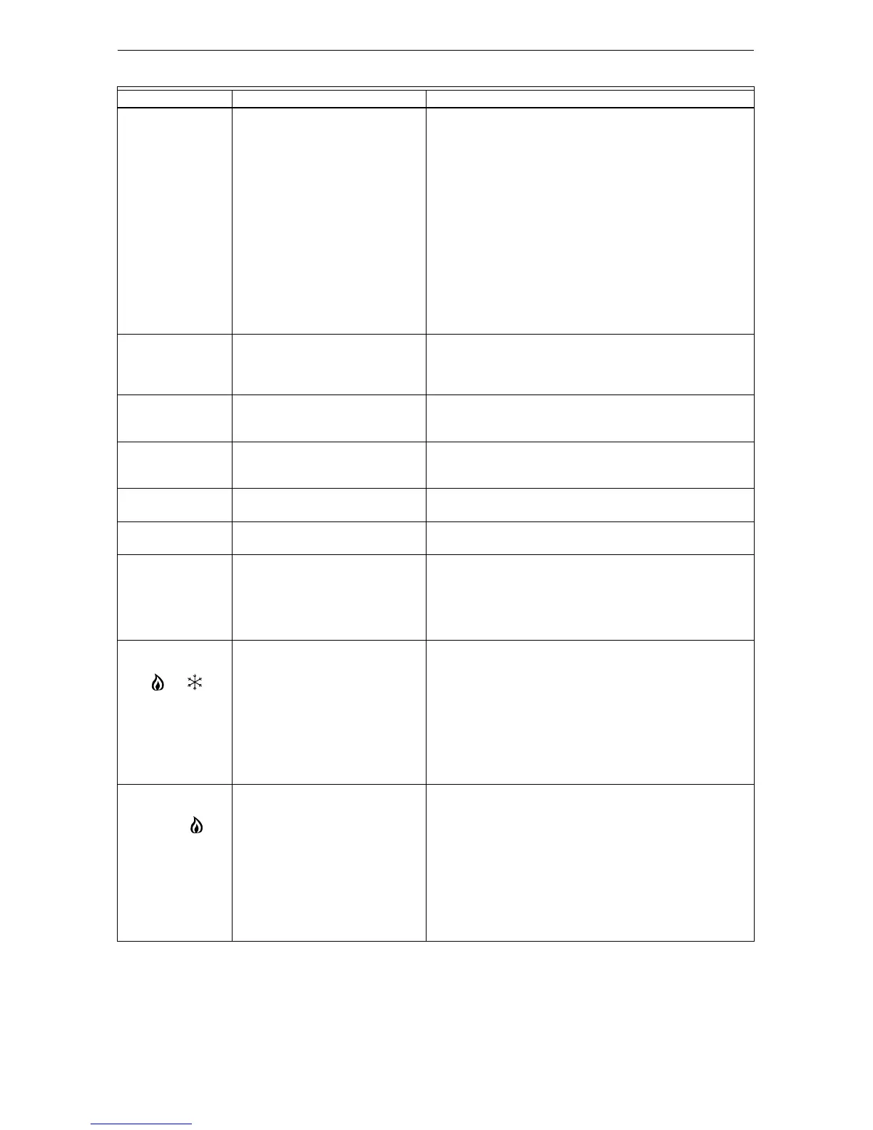
Table 10. Troubleshooting Information.
Symptom Possible Cause Action
Display does not
come on.
Thermostat is not being powered. Check if the thermostat is mounted and latched on the
wallplate; if not:
—mount and latch the thermostat on the wallplate.
Check if the circuit breaker is tripped; if it is:
—reset the circuit breaker.
Check if the fuse in the fuse box is blown; if it is:
—replace the fuse.
Check if the power switch at the equipment is in the Off
position; if it is:
—set to the On position.
Check for 24 vac on terminals 2 and 3:
—replace any broken wires.
If 24 Vac is present on terminals 2 and 3, replace the
thermostat.
“1 COM”, “2 COM”,
or “3 COM” is
displayed.
Thermostat is not communicating
correctly with the W8835 or
W8635A,B.
Check the connection to terminal 1 at the thermostat and
W8835 or W8635 EIM:
—replace any broken wires.
—cycle power.
“4 COM” is
displayed on left
side of the display.
More than one thermostat is set to
the same zone number.
Enter Installer Setup and change Installer Setup Number 1
to another value (1-3) that is different from the thermostat
with the same zone number.
5 COM Zone 0 was found in a zoned
system
Enter Installer Setup and change Installer Setup Number 1
to another value (1-9) that corresponds to the zone it is
controlling.
6 COM Zone 1 was not found. Enter Installer Setup on the Zone 1 Thermostat and
change Installer Setup Number 1 to 1.
7 COM System is configured to use
external timer.
The external timer function is not currently available. Enter
Installer Setup and change Installer Setup 43 to 0.
System switch
setting displays “off
only.”
During Automatic Discovery
mode, the thermostat did not
correctly set the number of heat or
cool stages.
Run Automatic Discovery mode by cycling power to the
equipment.
Manually run Discovery mode in Installer Setup.
Manually configure heat and/or cool stages (Installer
Setups 5, 8 and 9).
Thermostat is
calling for heat or
cool; or
displays and the
corresponding
damper does not
open.
Thermostat zone number is not
set to the corresponding W8703
zone number.
Terminal 1 on W8703 Damper
Interface Module is not properly
connected.
W8703 Damper Interface Module
is defective.
Set zone number at the thermostat to correspond with the
correct zone number for the W8703 Damper Interface
Module.
Properly connect terminal 1 on the W8703 Damper
Interface Module.
If the W8703 indicates the damper is closed (red LED
lights), replace the W8703 Damper Interface Module.
Heating does not
come on. System
on indicator
displays.
Communication is not being
completed.
Heat load at W8635 EIM is not
connected correctly.
End the call and repeat the call. Check the Flash Com OK
LED on the W8835 or W8635 EIM while the call is being
made.
If the Flash Com OK LED does not blink:
—check communication bus wiring.
If the Flash Com OK LED blinks correctly:
—check that 24 Vac is present at W1 or W1/Y1 terminal,
depending on which equipment module is being used.
If 24 Vac is not present, check the R to Rh connection. If
the connection is good, replace the W8835 or W8635 EIM.
 Loading...