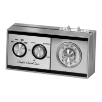
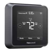
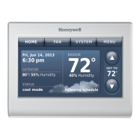
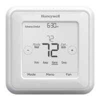
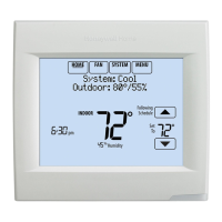
T8635L MICROELECTRONIC COMMUNICATING PROGRAMMABLE THERMOSTAT
17 69-1331—5
Cooling does not
come on. System
on indicator
displays.
Communication is not being
completed.
Cool load at W8635 EIM is not
connected correctly.
End and repeat the call for cool. Check the Flash Com OK
LED on the W8635 EIM or W8835 while the call is being
made.
If the Flash Com OK LED does not blink:
—check communication bus wiring.
If the Flash Com OK LED blinks correctly:
—check that 24 Vac is present at Y1 or W1/Y1 terminal,
depending on which EIM is being used.
If 24 Vac is not present, check R to Rc and/or Rh
connections. If the R to Rc and/or Rh connections are
good, replace the W8635 EIM or W8835.
“wait” is displayed
and the call for Cool
(or Heat when used
in a heat pump
application) has not
started.
Compressor protection is in effect. Compressor protection can be set from 0 to 5 minutes to
prevent compressor damage due to rapid cycling. Wait
until the compressor protection period expires.
To bypass compressor protection during the installation
phase, see the Installer System Test section.
2
nd
stage heat or
cool does not
energize (only
when used with
W8635A).
Stage configuration is not set
correctly to match the number of
selected stages.
Cool load at W8635 EIM is not
connected correctly.
Set the Stage configuration in Installer Setup for two stages
of heat and/or two stages of cool.
Check that 24 Vac is present at Y2, W2 or Aux. Terminal,
depending on EIM used. If 24 Vac is not present, all
connections are good and the thermostat is properly
configured, replace W8635A EIM or W8835.
Emergency Heat
does not energize
(only when used
with W8635B or
W8835).
Emergency Heat load at W8635
or W8835 is not connected
correctly.
Check that 24 Vac is present at E terminal. If 24 Vac is not
present, all connections are good, and the thermostat is
properly configured, replace W8635B or W8835.
Emergency Heat
can not be selected
with the System
switch (W8635B
only).
Stage configuration is not set
correctly to match the number of
stages selected.
Set the Stage configuration, Installer Setup No. 9 to 1, see
table 5 for one stage of Emergency Heat.
Fan does not come
on with a call for
electric heat.
Electric heat setting is not
configured.
Fan load at the W8835 or W8635
EIM is not connected correctly.
Set Installer Setup No. 4 to 1 for electric heat, see Table 6.
Check that 24 Vac is present at G terminal. If 24 Vac is not
present, all connections are good, and the thermostat is
configured, replace the W8635 EIM or W8835.
The is flashing
and the damper
does not open.
Thermostat is waiting for a call for
heat or cool to end in another
zone before opening this zone
damper.
Wait until call from other zone ends.
Temperature setting
does not change
(example: cannot
set the heating
higher or the
cooling lower).
The upper or lower temperature
limits are reached.
Check temperature setpoint limits; setpoint limit ranges
are:
—heating: 40° to 90°F (4.5° to 32°C).
—cooling: 45° to 99°F (7° to 37°C).
See Installer Setup no. 34 and no. 35 to change the
setpoint limits, see Table 6.
Fan runs
continuously.
Fan setting set to On or
programmed to On.
Pressing the Fan key changes the fan from On to Auto or
vice versa for the duration of the current program period.
To set the fan to run continuously for all periods, program
the fan to On for each period and day.
The green LED is
on.
Filter expired. Replace filter or clean electronic air cleaner cells. Press
and hold the filter key to reset the timer.
To disable the filter timer, select 0 as the timer value.
The red LED is on. Check LED. 24 Vac is present at
the L terminal on the W8835 or
W8635B EIM.
Check heat pump manufacturer instructions.
Table 10. Troubleshooting Information. (Continued)
Symptom Possible Cause Action

 Loading...
