WEB/CP-202-XPR AND WEB/CP-602-XPR CONTROLLERS
19 95-7775—01
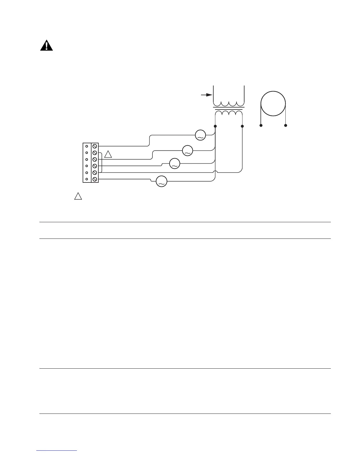
Relays are not rated for AC mains (line level) powered loads – 24V @ 0.5A is the maximum switched load. Use an
external 24V transformer or a 24 Vdc power supply to power loads.
Use a RelayOutputWritable in the station for each output. Fig. 14 shows an example wiring diagram.
Fig. 14. Relay output wiring diagram.
NOTE: The two common DO terminals (2C1, 3C4) are isolated from each other. This is useful if controlled loads 1 and 2 are
powered from a different circuit/source than loads 3 and 4.
An LED status indicator for each relay output (K1–K4) is visible on the left cover, and also on the board. Under normal operation,
an On status indicates that the load is powered. See About LEDs on page 25 for more details.
Nrio16Module (Software) Representation
In the Niagara
AX
station interface to the WEB/CP-202-XPR or WEB/CP-602-XPR, the controller’s onboard I/O is modeled in the
station’s M2mIoNetwork (copied from the nrio palette), under a child Nrio16Module “device level” component. This
Nrio16Module has a default name of “LocalIo16”.
• If there are no remote I/O modules (IO-16-REM-H) this is the only Nrio network needed in the station.
The M2mIoNetwork has a fixed “Port Name” property of COM3, and a “Trunk” property of 1.
• If any remote I/O modules are connected to the controller’s RS-485 port, the station needs an additional NrioNetwork, with a
“Port Name” property of COM2, and “Trunk” property of 2. For more details, see the
NiagaraAX NRIO Guide. For wiring details,
see
Wiring to Remote I/O Modules on page 23
. Note that a maximum of three IO-16-REM-H modules is recommended for a
WEB/CP-202-XPR, due to platform resource considerations.
After remote I/O modules are discovered and added to the station under this separate NrioNetwork (each as one as an
Nrio16Module), the serial status LEDs for the controller’s RS-485 port (S2TX, S2RX) continually flash, reflecting polling
activity. See About LEDs on page 25 for more details. Also, the “STATUS” LED on each remote I/O module lights solid green.
NOTE: Any time a remote I/O module’s status LED is not lit solid green, all of its outputs are in “fail-safe” state (all relay outputs
OFF, and all AOs are at a 0-volt level).
Blinking of a remote I/O module’s status LED occurs for two reasons, shown at different rates:
- Rapid flash (low duty cycle), meaning the unit is unconfigured. Discovery and addition to the station database is
required.
- Equal time on and off (50% duty cycle), meaning the unit is configured, but currently offline with the controller. Check
RS-485 wiring between the controller and remote I/O module.
3C4
NO4
NO3
NO2
NO1
1C2
24 VAC LOADS
M28876
24 VAC TRANSFORMER
(SEE PREVIOUS WARNING)
AC LINE (MAINS)
THE TWO COMMON TERMINALS (3C4, 1C2) ARE ISLOATED FROM EACH OTHER.
IF POWERING PILOT LOADS FROM A SINGLE 24 V SOURCE, YOU CAN JUMPER THEM TOGETHER AS SHOWN.
1
1
24 VAC
24 VDC
24 VDC POWER SUPPLY
USE POINT: RelayOutputWritable
1
4
3
2

 Loading...