WEB/CP-202-XPR AND WEB/CP-602-XPR CONTROLLERS
7 95-7775—01
Physical Mounting
• For proper cooling, mount the controller vertically, with the two screw mounting tabs at the bottom of the unit. It is not
necessary to remove the covers before mounting.
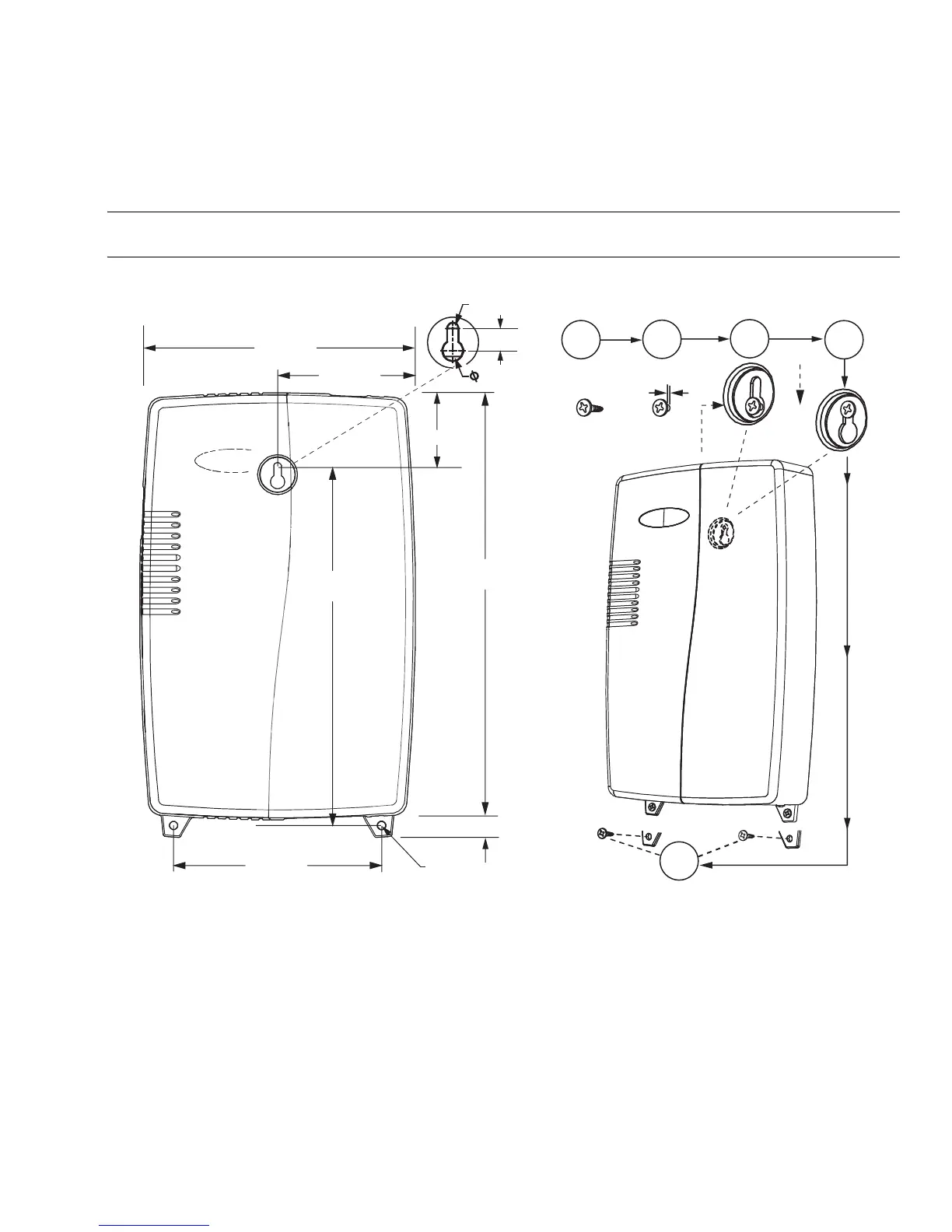
• Dimensions of the rear keyhole slot and lower mounting tabs are shown in Fig. 2, along with a step-by-step wall mounting
procedure.
NOTE: Install one panhead screw (intended for the rear keyhole slot) into the wall first, then hang the controller on that screw.
Then use screws in the two lower tabs to secure. See Fig. 2.
Fig. 2. WEB/CP-202-XPR or WEB/CP-602-XPR controller wall mounting dimensions in inches (mm) and details.
To mount unit on wall.
1. For the rear center keyhole slot, install a pan head screw into the wall (1a in Fig. 2). Do not tighten completely. Leave the
back of the screw head about 3/32 in. (2.4mm) from the wall (1b in Fig. 2).
2. Position the unit over the screw (2a in Fig. 2), entering the screw head into the keyhole slot in the back of the unit.
3. Pressing the unit against the wall, slide it down so the screw is captured by the slot (2b in Fig. 2).
4. Level the unit, and install a screw into each of the two lower mounting tabs (3 in Fig. 2).
7.75 (197)
39.4 (100)
2.125 (54)
12.03 (306)
0.59 (15)
2 x
0.225 (5.7)
5.9 (150)
R. 0.1 (2.54)
0.433 (11)
0.41 (10.4)
M29987
1a
1b
2a
2b
3
3/32 (2.4)
10.16 (258)

 Loading...