WEB/CP-202-XPR AND WEB/CP-602-XPR CONTROLLERS
9 95-7775—01
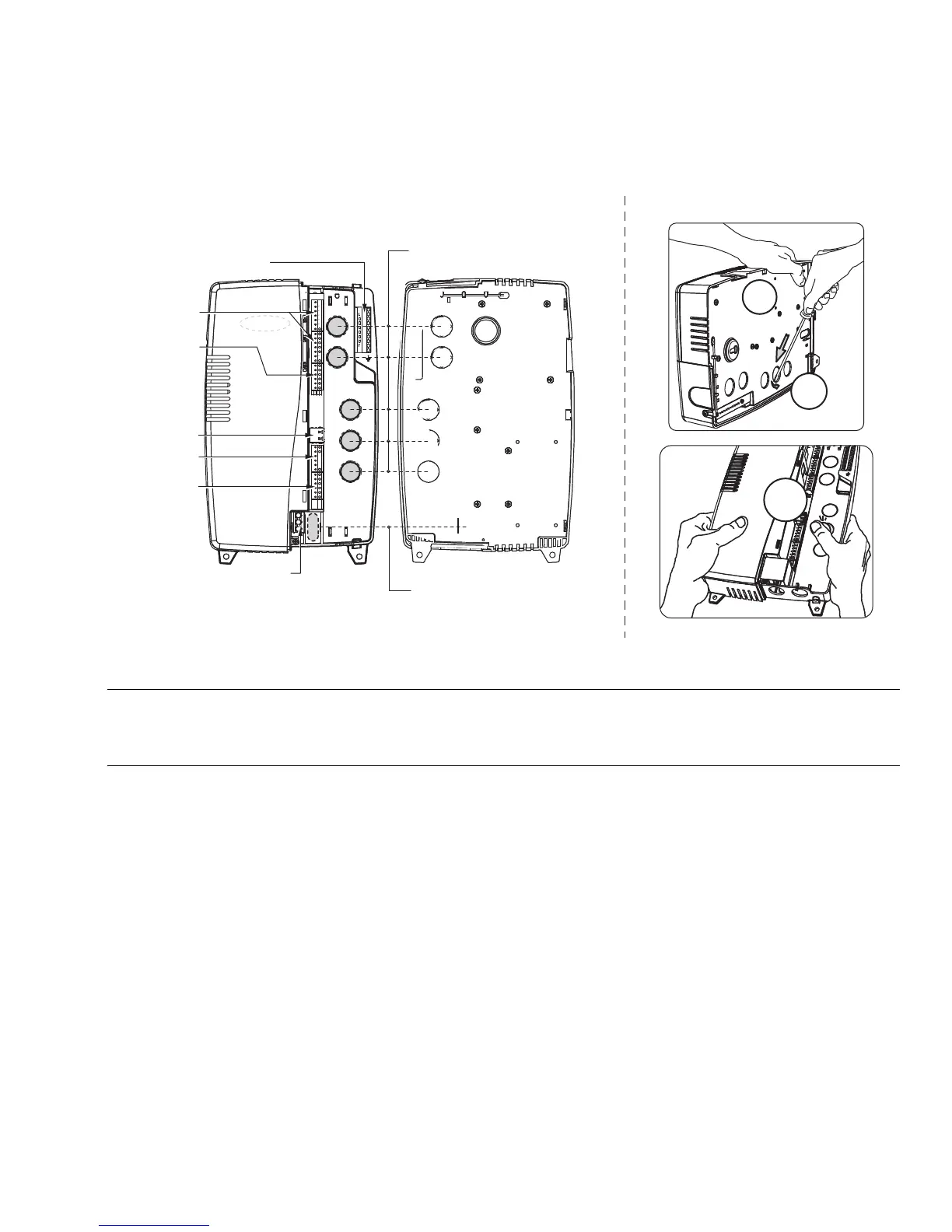
Locate and remove chassis knockouts
The WEB/CP-202-XPR or WEB/CP-602-XPR has six (6) wiring knockouts on the back of the plastic chassis (see Fig. 4):
• Five (5) round, 0.945 in. (24 mm) diameter, for general wiring of controller terminals and I/O points.
• One (1) oval, 0.46 in. (11.7 mm) wide x 1.25 in. (31.7 mm) high, for wiring 24V input power and ground.
Fig. 4. Wiring knockout details.
NOTE: In addition to these rear knockouts, there are two wiring holes, 0.845 in. (21.5 mm) for general wiring—one on the top
side, one on the bottom side. The top hole has an associated “U-shaped knockout” atop the right cover. Also, an
additional wiring hole is at the bottom 0.865 in. (22 mm), available for wiring 24V input power and ground. Usage of
wiring knockouts and holes will vary by installation.
Remove the appropriate knockouts, as needed, before mounting to the wall. Note that the shielded 24V power input wiring area
has a hole on the bottom side, as well as an oval-shaped knockout on the rear of the chassis. If necessary, install any conduit or
cable clamps to knockout holes.
Locate and remove chassis knockouts.
1. To remove a rear knockout:
a. Hold the unit with its knockout side on flat work surface, as shown in Fig. 4 (1a).
b. From the back, wedge a straight-blade screwdriver into the knockout edge, and twist to pry open as shown in
Fig. 4 (1b).
2. Remove the right-side cover (see Removing and Replacing the Covers on page 8).
Press up each opened knockout with your finger and thumb as shown in Fig. 4 (2), then twist and remove.
FRONT RIGHT COVER REMOVED
KNOCKOUTS: QTY 5; 0.954 (24) DIA.
GROUNDING TERMINAL STRIP
UNIVERSAL
INPUTS (UI)
RS-485 / 15VDC
POWER OUT
DIGITAL
OUTPUTS (DO)
ANALOG
OUTPUTS (AO)
RS-232
KNOCKOUT: ONE (1)
0.46 (11.7) WIDE x 1.25 (31.7) HIGH
M28866
24 V POWER AND EARTH GROUND
(SHIELD REMOVED)
REMOVING CHASSIS KNOCKOUTS
1a
1b
2

 Loading...