COMPACT VAV CONTROLLER WEB-VA423B24N – INSTALLATION INSTRUCTIONS
11 31-00362-01
Physical limitation:
32 loads as per TIA/EIA-485 standard. One
Spyder Model 5 controller represents ¼ load.
The physical limitation is important in case 3rd
party devices representing a full load are
connected.
AutoMAC limitation:
We have tested with a maximum of 64 for
maxMaster. A maxMaster of 64 means we
support a maximum of 62 Spyder Model 5 VAV
controllers, one supervisor, and one BACnet
client (tool) per BACnet MS/TP channel. The
default value for maxMaster is 35, as this is the
maximum supported by some plant controllers.
In the event that you have a plant controller
capable of supporting more than 35 devices, it
will therefore be necessary for you to increase
the maxMaster setting to the actual required
number of devices (e.g., to the maximum
number of 64). Refer to the Spyder Model 5 –
Engineering Tool User Guide for more
information on how to do this.
Thus, depending upon your actual performance
needs and required communication rates, it is
recommended to connect a smaller number of
BACnet MS/TP devices per channel.
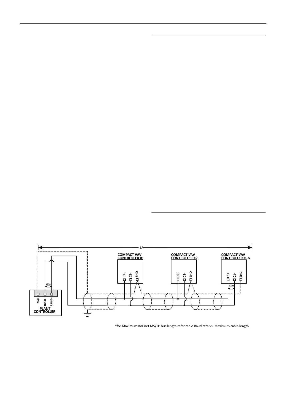
• Matched terminating resistors are
required at each end of a segment bus
wired across (+) and (-). Use matched
precision resistors rated ¼ W ±1% / 80 -
130 Ω. Ideally, the value of the
terminating resistors should match the
rated characteristic impedance of the
installed cable. For example, if the
installed MS/TP cable has a listed
characteristic impedance of 120 Ω,
install 120 Ω matched precision
resistors.
• Following proper MS/TP cabling shield
grounding procedures is important to
minimize the risk of communication
problems and equipment damage
caused by capacitive coupling.
Capacitive coupling is caused by placing
MS/TP cabling close to lines carrying
higher voltage. If shielding is used, the
shielding of each individual bus segment
should be separately connected at one
end to earth.
 Loading...