COMPACT VAV CONTROLLER WEB-VA423B24N – INSTALLATION INSTRUCTIONS
31-00362-01 14
During the automatic MAC addressing process,
LED behavior (See Table 8 on pg. 14) is displayed.
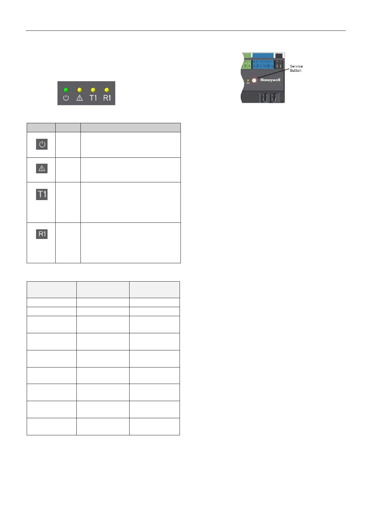
OPERATOR INTERFACE LEDs
The controller features the following LEDs:
Table 7. Description of LED behaviors
*Please return the controller for repair. Contact
Honeywell WEBs Customer Care for assistance.
The ON/OFF frequencies listed in Table 8 above
can be converted from "Hz" (i.e., "ON/OFF per
second") to "ON/OFF per minute" by multiplying
them by 60.
Service Button
The Service Button is used to trigger dedicated
events.
It is important to distinguish different controller
behaviors which are elicited depending upon
whether the Service Button is pressed when the
controller is powering up or when it is in normal
operation. See the following dedicated events.
Pressing Service Button during Power-Up
During controller power-up, pressing the Service
Button until LED behavior (See Table 8 on pg.14) is
displayed will reset the controller to its factory
settings, which are as follows:
• The application is cleared from the controller.
• The MAC address will be set to 0xFF, meaning
that the controller will now search for a new
mac address (Auto-MAC will be automatically
triggered after controller power-up).
• The maxMaster setting will revert to its default
value of 35.
• The Max info frames will revert to 10.
• The device instance will revert to its default of
4194302.
• The device name will revert to WEB-
[ModelName].
• The values of Auto MAC, Min MAC and Max
MAC will be reset to 1 and maxMaster,
respectively.
Pressing Service Button during Normal Operation
During normal operation of the controller, a short
press (< 1 sec) of the Service Button will cause a
Service Pin Message (BACnet WhoAmI as a Private
Transfer (SerialNo. = 130)) to be sent.
 Loading...