XNX Universal Transmitter
Installation and Operation
75
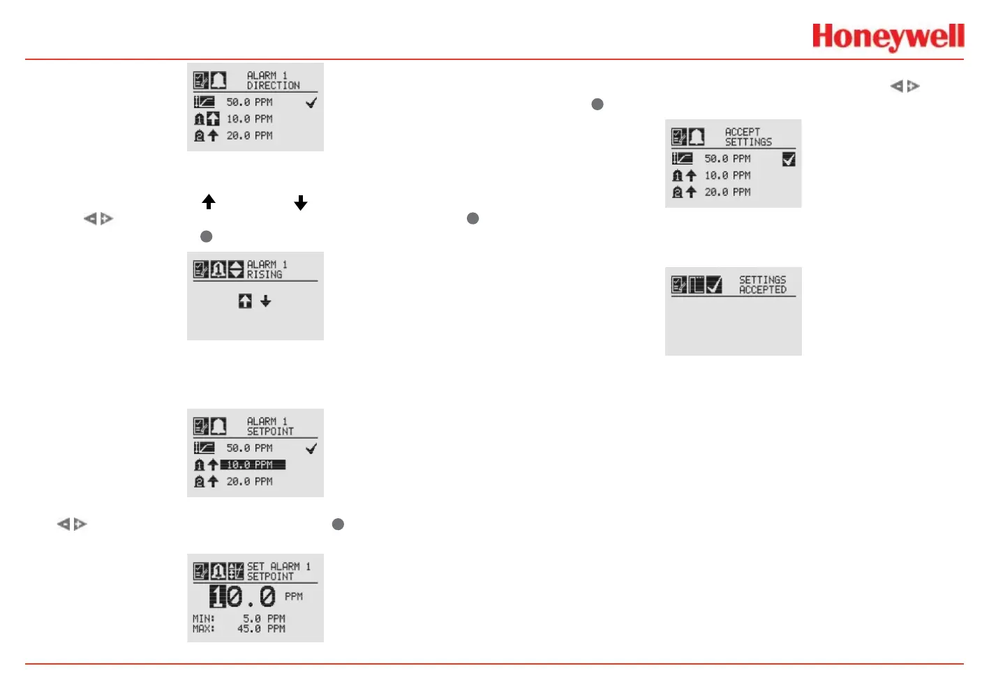
Figure 85. Alarm Direction screen
The icons next to the bell images indicate whether the alarm has
been triggered by rising (
) or falling ( ) gas concentrations.
Use the
switches to highlight the appropriate trigger. Use
✓
to make the selection or
✖
to discard it.
Figure 86. Setting alarm rising/falling
The Alarm Limits selection sets the alarm trigger level for both
alarms.
Figure 87. Alarm Limits screen
Use to set the desired alarm limit and
✓
select it. Repeat
for each alarm.
Figure 88. Setting an alarm setpoint
When complete, the display will return to the main Range &
Alarm screen. When all settings have been made, use
to
move to the
✓
on the display to Accept Settings.
Figure 89. Accept Settings screen
When the settings have been saved, the following screen will
appear on the display.
Figure 90. Settings Accepted screen
See Specications for detailed EC cell information.
 Loading...


