XNX Universal Transmitter
Proof Testing Procedure
12
Testing
3. Refer to Table 6 for the mA levels. If the values do not
match the values in the table, proceed to step #4 to adjust
the values.
NOTE
If the values for the faults and warnings have been changed
from the default settings since installation, ensure the current
output matches those changed values.
Table 3. Set mA Levels
Signal*
Output (mA)
Default Min Max
I Inhibit 2.0 mA 1.0 3.5
W Warning 3.0 mA 1.0 3.5
O Overrange 21.0 mA 20 22
B** Beam Blocked 1.0 mA 1.0 4.0
L** Low Signal 1.0 mA 1.0 4.0
*Faults are set to 1 mA and are not user-selectable
**Beam blocked and Low Signal apply only to Excel sensors.
4. Using the switches, increment or decrement the value
until the desired value appears. Then use
✓
to conrm the
value and move to the next setting. Repeat for each setting
that must be changed.
The available output range for Inhibit, Warning, Beam Blocked and
Low Signal is from 1.0 to 4.0 mA and for an overrange condition,
the range is 20.0 to 22.0 mA. Refer to Section 5 Warnings/Faults
in the XNX Technical Manual for more information.
5. Once all changes have been made, use the switches
to move to the ‘3’ and use
✓
on the front panel to save the
settings.
Figure 14. mA Settings Saved
NOTE:
If ‘3’ is not selected, none of the changes will be saved.
6.4 Testing
6.4.1 Fault and Alarm State
The mA output of the faults and alarm states should be simulated
and the current output at the controller end should be within
tolerance. Refer to Table 6 for the current values for the fault and
alarm states.
1. From the Test Menu, select Alarm/Fault Simulation.
Figure 15. Alarm/Fault Simulation Screen
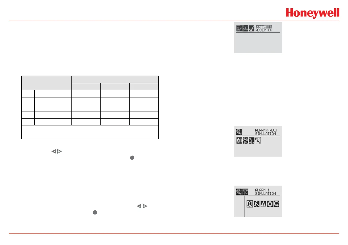
2. Figure 16 shows the menu choices simulating Alarm 1, Alarm
2, Warning, or a Fault. Selecting the return arrow icon will
display the Alarms/Fault Reset Menu.
Figure 16. Alarm/Fault Simulation Menu
3. Selecting an alarm level to simulate will activate a
 Loading...


