Do you have a question about the horiba APSA-370 and is the answer not in the manual?
Details HORIBA's warranty terms, limitations, and responsibilities for the product.
Generally, company names and brand names are registered or trademarks of respective companies.
Specifies the required installation environment, including categories and pollution degree.
Guides on proper disposal of WEEE and batteries according to EU directives.
Explains compliance with FCC rules for digital devices and potential interference.
Explains the meaning of DANGER, WARNING, and CAUTION signals used in the manual.
Describes symbols indicating actions to be followed or prohibited.
Advises following local laws for product disposal.
Explains the meaning of Note, Reference, and Tip indicators used throughout the manual.
Accesses data review (average, integration) and history logs (calibration, alarm).
Manages analog I/O, hour meter, lamp history, and output range configurations.
Configures LCD, password, data save, machine ID, and TCP/IP settings.
Allows locking/unlocking the keys to prevent unintended operations.
Details specifications for terminal blocks, contact points, and analog outputs.
Describes contact inputs/outputs for AIC, alarms, maintenance, and power status.
Explains the ultraviolet fluorescence (UVF) method used for SO2 measurement.
Lists detailed instrument specifications and provides an unpacking checklist.
Guides on proper installation environment and placement of the instrument.
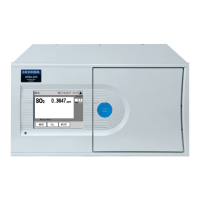
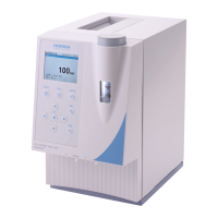
Introduces the APSA-370 as an ambient SO2 monitor using UVF method.
Illustrates the system configuration of the APSA-370 with connected components.
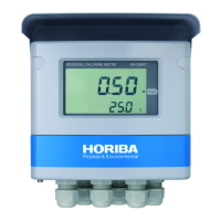
Identifies and describes components on the front panel of the APSA-370.
Identifies and describes components on the rear panel of the APSA-370.
Guides on powering on the device and the initial warm-up process.
Details the procedure for safely shutting down the APSA-370.
Outlines the step-by-step flow for initial setup and operation of the instrument.
Explains icons, time, key lock status, range, measurement results, and function keys.
Explains the AIC mode icon and the saving data icon.
Shows the current range status and measurement results.
Indicates the active measurement line and describes function keys.
Describes screens used for automatic and manual calibration procedures.
The basic screen for performing calibration, showing mode, values, and keys.
Details span value, zero/span coefficients, and function keys.
Allows switching the measurement line (MEAS, SPAN, ZERO, EXTERNAL).
Allows entering span gas concentration, zero/span coefficients using a keypad.
Guides on preparing for calibration, including entering span gas concentration.
Guides on entering the span gas concentration value for calibration.
Guides on preparing for calibration, including entering span gas concentration.
Guides on entering the span gas concentration value for calibration.
Explains AIC for automatic zero and span calibration based on set intervals or commands.
Details how to configure AIC settings like mode, start time, limit, and interval.
Explains AIC for automatic zero and span calibration based on set intervals or commands.
Details how to configure AIC settings like mode, start time, limit, and interval.
Explains AIC for automatic zero and span calibration based on set intervals or commands.
Sets the scheduled time for the next AIC sequence to begin.
Explains AIC for automatic zero and span calibration based on set intervals or commands.
Defines the time window available for starting the AIC sequence.
Explains AIC for automatic zero and span calibration based on set intervals or commands.
Sets the time interval for periodic AIC sequence starts.
Provides precautions for setting the AIC sequence.
Explains how the AIC start time is automatically corrected based on set limits.
Guides on setting the wait time, hold time, and calibration execution for the AIC sequence.
Guides on setting the wait time, hold time, and calibration execution for the AIC sequence.
Shows an example diagram of the AIC sequence process.
Details how to manually initiate the AIC sequence using the [AIC] key.
Outlines the step-by-step process for manual calibration.
Guides on performing manual zero and span calibration.
Guides on performing zero calibration and updating the coefficient.
Guides on performing manual zero and span calibration.
Guides on performing span calibration and updating the coefficient.
Guides on performing manual zero and span calibration.
Describes the final steps to complete calibration and resume measurement.
Explains how average, integration, and rolling average data are calculated and displayed.
Describes common functionalities for checking acquired data on various screens.
Explains how to delete calculated average and integration data.
Details the three types of average calculations and their display.
Explains timing considerations for average calculation, including power shutdowns.
Explains how integration data is calculated and displayed.
Discusses integration reset settings and clock adjustments.
Explains how rolling average values are calculated and displayed.
Lists functionalities accessible via the MENU key, covering data, history, maintenance, range, setting, system, and communication.
Describes the function of locking/unlocking keys.
Explains how to access various menu screens like DATA, HISTORY, MAINTENANCE, etc.
Allows checking average, integration, and rolling average data.
Used to display calibration and alarm history.
Describes how to delete history records.
Displays the history of calibration adjustments and alarms on the instrument.
Displays the history of Automatic Calibration (AIC) sequences.
Accesses screens for analog output, input, hour meter, and lamp history.
Guides on checking and changing the analog output modes.
Details the procedure for adjusting the zero output of the analog signal.
Details the procedure for adjusting the span output of the analog signal.
Displays analog input values for checking sensor and signal statuses.
Shows cumulative operating hours of consumables and allows resetting.
Displays recorded lamp voltage history, showing voltage and time.
Explains how to delete recorded lamp voltage data.
Allows changing analog output ranges by adjusting full-scale settings.
Allows changing analog output ranges by adjusting full-scale settings.
Guides on selecting and setting the desired range for analog output.
Displays and allows setting the range for analog output 1 (momentary value).
Displays and allows setting the range for analog output 2 (rolling average).
Accesses screens for time adjustment, AIC settings, integration reset, and unit conversion.
Accesses screens for time adjustment, AIC settings, integration reset, and unit conversion.
Allows adjusting the instrument's internal clock.
Accesses screens for time adjustment, AIC settings, integration reset, and unit conversion.
Configures integration reset method, time, and telemeter alarm.
Accesses screens for time adjustment, AIC settings, integration reset, and unit conversion.
Displays current concentration and conversion results, allows changing factors.
Accesses screens for time adjustment, AIC settings, integration reset, and unit conversion.
Guides on changing the unit conversion factor value using a numeric keypad.
Accesses screens for LCD settings, touch panel adjustment, password, and data saving.
Configures automatic backlight turn-off time and LCD brightness.
Guides on adjusting the touch panel positions for accurate input.
Details the procedure for changing the instrument's password.
Details the procedure for changing the instrument's password.
Guides on manually saving data to the memory before powering off.
Accesses settings for machine ID and TCP/IP.
Allows setting the machine identification code for communication.
Guides on changing the machine ID value.
Explains that a restart is needed for the changed machine ID to take effect.
Allows configuration of IP address, subnet mask, and default gateway.
Guides on changing the IP address using a numeric keypad.
Guides on changing the subnet mask value using a numeric keypad.
Guides on changing the default gateway value using a numeric keypad.
Explains that a restart is needed for TCP/IP settings to take effect.
Allows locking/unlocking the instrument keys and entering supervisor mode.
Details how to enter the password to unlock keys or access supervisor mode.
Guides on turning ON the maintenance switch before performing maintenance.
Provides instructions and frequency for replacing the filter element.
Lists consumables and their recommended replacement periods.
Explains how to check the current alarm status via the ALARM screen and indicator.
Explains how to check the current alarm status.
Explains how an alarm icon indicates data acquired during an alarm occurrence.
Lists various alarms, their status, and possible causes.
Lists alarms related to calibration and sensor failures.
Lists alarms related to temperature sensor, lamp intensity, and pressure.
Lists alarms for flow rate, I2C communication, and CF data logging issues.
Provides general troubleshooting steps for no output or low/high output signals.
Addresses issues with unstable readings and high noise levels.
Details specifications for terminal blocks, contact points, and analog outputs.
Describes how the current momentary value range is output.
Explains the functions of contact inputs for AIC start and telemeter failure.
Describes contact outputs for AIC progress, maintenance mode, and alarms.
Indicates when calibration errors, general errors, or power status changes.
Allows setting analog output data to various measurement values.
Explains the ultraviolet fluorescence (UVF) method for SO2 measurement.
Lists detailed technical specifications of the APSA-370 instrument.
Provides a checklist for items included in the package.
Specifies the required ambient conditions for installing the instrument.
Guides on selecting suitable places for instrument installation like racks or desktops.
Lists references for external dimensions, flow sheets, and signal tables.
| Brand | horiba |
|---|---|
| Model | APSA-370 |
| Category | Measuring Instruments |
| Language | English |