
J
Jesus BaldwinAug 1, 2025
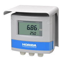
Why won't my Horiba Measuring Instruments turn on?
- SShannon LopezAug 1, 2025
If your Horiba Measuring Instruments device isn't powering on, first check the power supply voltage to ensure it's within the rated range. Then, inspect the power supply wiring for any faults. If these steps don't resolve the issue, it may indicate an internal abnormality or a blowout, and you should contact support.