24
TR10A108-B RE / 02.2013
Electrical connection4
Note the safety instructions in
▶
section 2.6
– Mains voltage
– External voltage at the connecting
terminals
To prevent malfunctions:
Duct the operator's connection
▶
cables (24 V DC) in an installation
system that is separate from other
supply lines (230 V AC).
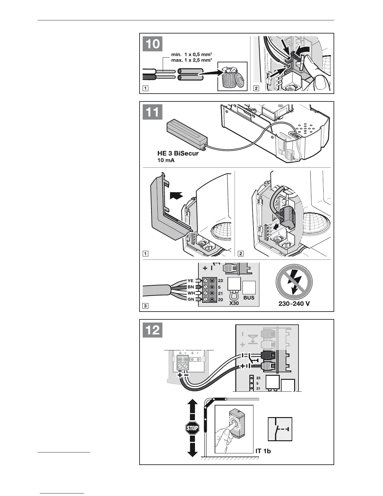
Connecting terminals4.1
All connecting terminals can have
multiple assignments (see figure 10):
Minimum thickness: 1 × 0.5 mmō
2
Maximum thickness: 1 × 2.5 mmō
2
Accessories with special functions can
be connected to the BUS connecting
terminal.
Connecting additional 4.2
components / accessories
NOTE:
Maximum operator current rating by all
accessories: max. 250 mA. See the
figures for component power
consumption.
External radio receiver*4.2.1
See Figure
▶
11 and section 9
Insert the plug of the receiver in the
corresponding socket.
External impulse button4.2.2
See Figure
▶
12
One or more buttons with normally open
contacts (volt-free), such as internal
push buttons or key switches, can be
connected in parallel.
* Accessory, not included as standard
equipment!
ENGLISH