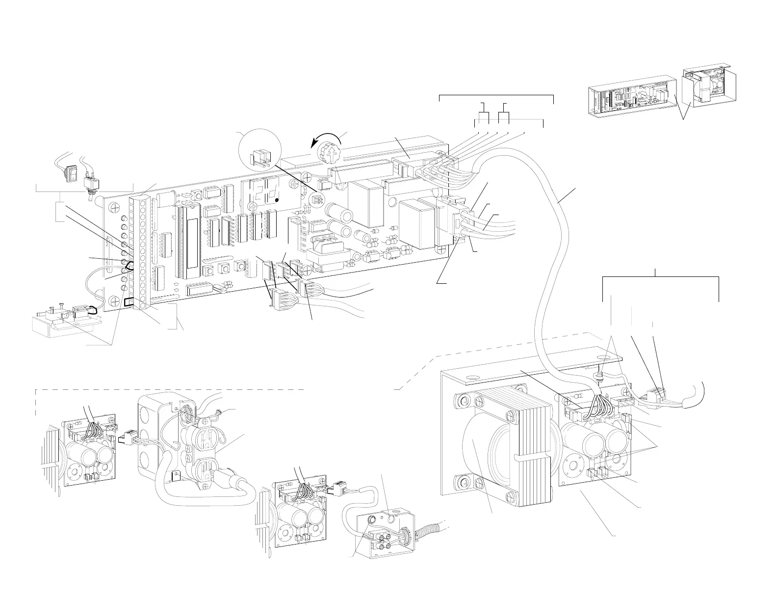
CN 7
TO
AUTOLOCK
FIELD WIRING
OPTION 2
TO
ENCODER
The encoder must be plugged into
CN1 on the control.
To get the operator up and running, check the items outlined below-
Set the reversing sensitivity
fully counter-clockwise.
F
2
F
3
F
1
Field wiring options
1. SERIES 2000B, 2001, 2003 & 2004 SLIDE OPERATOR QUICK START INSTRUCTIONS
If the day / night mode is
NOT
to be used - there
MUST
be a
jumper between 15 & 16.
See Sections 5 thru 10 for actuating
features and lock set-up.
With wiring option 1, 2 or 3
The main ground wire must secured using
the green grounding screw.
F
2
F
3
F
1
3rd Step
IMPORTANT
2.187d3
The close monitor switch must
be connected to #10 & #11 of CN2.
The switch must trip when the door is
fully closed.
2nd Step
15
16
FIELD WIRING
OPTION 3
Grounding
screw
Grounding
screw
4th Step
Do
NOT
wire any motion detectors or any other accessories at this time.
Factory pre-wired beams (pins 5,6 & 7) may be left in place.
10th Step
Verify jumpers JB1A & JB1B
are NOT installed on rev. E and
later controls.
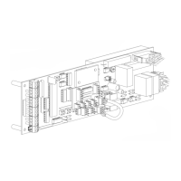
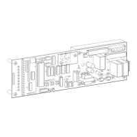
C2150 Control with version 2 software (Revision E or later hardware)
2001
switch
11
10
9
8
2003
switch
V-XXXX
CN 2
D
1
A toggle switch or jumper must
be present between pins 8 & 9.
Switches are sent loose and field
mounted. Break-outs are wired in
series with the toggle switch .
1st Step
CN 1
CN 4
C
N
5
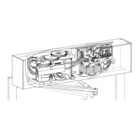
Belt drive
(ENC)
9th Step
The motor must be
plugged into connector
CN8
Neutral WHT U.S. - BLU Int.
H202.1
F
2
POWER SUPPLY
C3925 for 120VAC-2001 (shown)
C3955 for 120VAC-2003
C3926 for 240VAC-2001
C3956 for 240 VAC-2003
CN 2
Master
fuse
F 1
+27 to +35VDC
& processor
NOTE:
Component arrangement
may vary.
Motor
+100 to +120
VDC
All fuses are
5x20 mm Type "T"
Rated 3.15 amp
F 2
F
3
F 3
CN 1
FIELD WIRING
OPTION 1
AC POWER IN
Line (Hot side)
BLK U.S. - BRN Int.
F
1
2
3
1
7th Step
A 5 conductor cable attaches
CN7 to the power supply.
5th Step
BLK
CN 8
GRN / YEL
motor ground
TO
MOTOR
RED
1 2 3 4 5GND
8th Step
Check incoming voltages
from power supply
+120 to +100
VDC from F2
+27 to + 35
VDC from F3
NOTE:
On 2001 & 2003
Metal shields are
REQUIRED
by UL
for protection againest
high voltage areas
Do not remove.
Ground GRN U.S. - GRN / YEL Int. (
Connect to grounding screw)
Check that the incoming power
is wired as shown.
6th Step
Shields and chassis
are not shown in this
manual for clarity
 Loading...