PREPARETHE OPENING (cont%l)
Flooring
Under the Range
Your range, like many other household
items, is heavy and can settle into soft
floor coveringssuchas cushionedvinylor
carpeting.
VVhenmovingthe range on this type
of flooring, use care, and follow these simple and
inexpensive instructions.
The range should be installed on a 1/4 inch thick
sheet of plywood (or similar material) as follows:
When the floor covering endk at the front of the
range, the area that the range will rest on should
be built up with plpvood to the same level or
higher than the floor covering. This will allow
the range to be moved for cleaning or servicing.
STEP2
PREPARE FOR ELECTRIChl CONNECTION
Use only a 3-conductor, or if required a 4
conductor range cord set as noted below. These
cord sets are provided with ring type terminals.
The electrical rating of the cord must be 125/250
volts minimum, 40 amperes.
NCYI’E:Only a 4conductor cord is to be used
when the appliance is installed in a mobile home
or where local codes do not permit grounding
through the neutral.
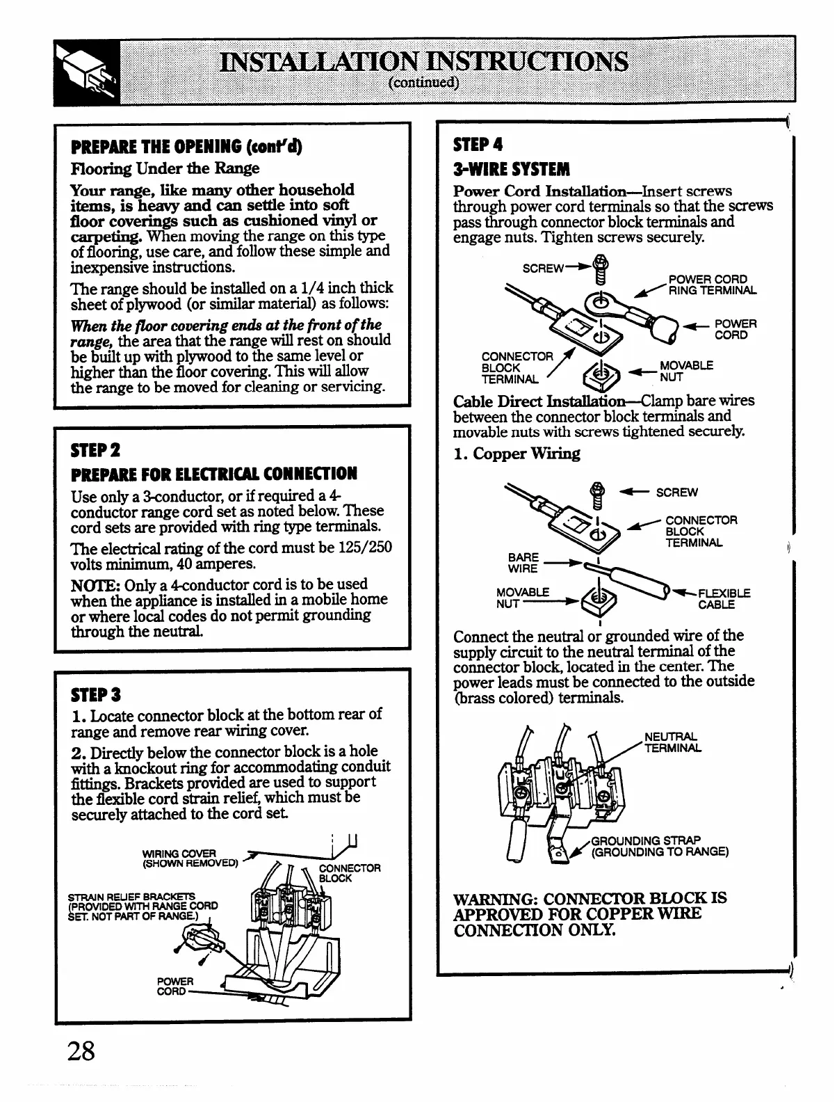
STEP 3
1. ~cate connector block at the bottom rear of
range and remove rear wiring cover.
2. Directly below the connector block is a hole
with a knockout ring for accommodating conduit
fittings. Brackets provided are used to support
the flexible cord strain relie~ which must be
securely attached to the cord set
TOR
STEP4
3-WIRE SYSTEM
Power Cord Installation-Insert screws
through power cord terminals so that the screws
pass through comector block terminals and
engage nuts. Tighten screws securely.
Cable Direct Installation-Clamp bare wires
between the connector block terminals and
movable nuts with screws tightened securely.
1. Copper Wtig
Connectthe neutral or mounded wire of the
supply circuit to the netitral terminal of the
comector block, located in the center. The
power leads must be connected to the outside
(brass colored) terminals.
NEUTRAL
TERMINAL
~ I&
GROUNDING STRAP
(GROUNDING TO RANGE)
W~G: CONNEC’IllR B~CK IS
APPROVED FOR COPPER WIRE
CONNEC.I’ION ONLY.
1)
28