EasyManuals Logo

HotSpring HIGHLIFE Series Pre-Delivery Instructions

HotSpring HIGHLIFE Series
20 pages
To Next Page IconTo Next Page
To Previous Page IconTo Previous Page
Page #15 background imageLoading...
Page #15 background image
Page 15 Pre-Delivery Instructions
Strip wire
insulation back
½”
Entire stripped
end of wire
must be inside
Terminal
Block
After step 6,
pull on wire to
ensure proper
installation
Remove
screwdriver
Install
Stripped end
of wire into
Terminal
Block
Push top of
screwdriver away
from wire
Terminal Block
Insert
screwdriver to
engage cage
clamp
4
6
1/2”
3
5
3
WIRE INSTALLATION
FOR CONTROL BOX TERMINAL BLOCK
(Layout of Spa’s Terminal Blocks may vary)
Wire Installation Steps
Refer to spa’s wiring
diagram on back of Control
Box Cover for proper wiring
and jumper conguration!
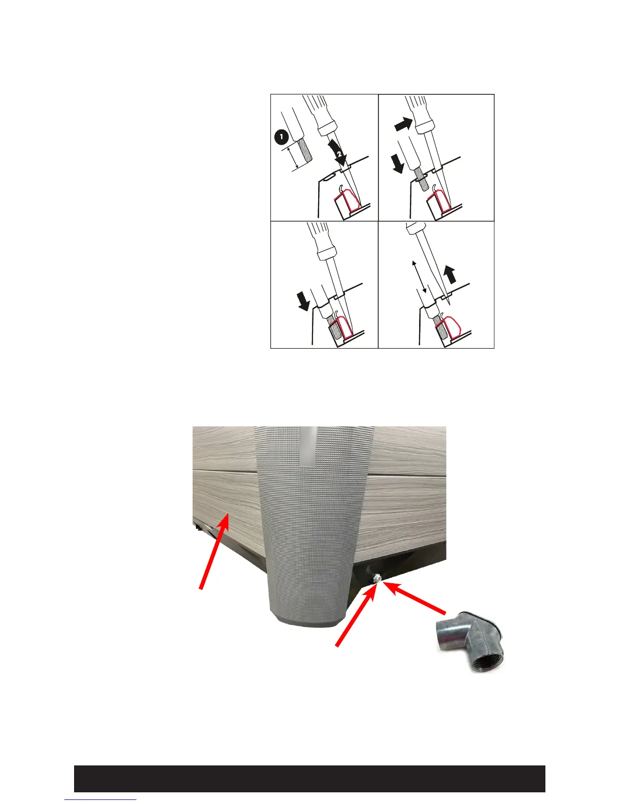
ELECTRICAL ACCESS INTO SPA
Recommended: Attach
3/4" (1.9 cm) Pull elbow to
Electrical access on left or
right side of spa
3/4" (1.9 cm) threaded Electrical
access (right side of spa).
NOTE: Electrical access is also
available on left side of spa
Front of spa
(Dock side)
(1.3 cm).

Other manuals for HotSpring HIGHLIFE Series

Questions and Answers:

Question and Answer IconNeed help?

Do you have a question about the HotSpring HIGHLIFE Series and is the answer not in the manual?

HotSpring HIGHLIFE Series Specifications

General IconGeneral
Water Care SystemFreshWater Salt System
LightingLED lighting
PumpVaries by model
Filtration SystemTri-X filter
WarrantyVaries by model (5-7 years)
Jet CountVaries by model (approx. 35-50 jets)

Related product manuals