Page 11 Pre-Delivery Instructionsx Page 11 x
NOTE: Canadian regulations prevent Pace
™,
Stride, SX spas to come with a power cord and are require to
be wired directly to the power source. Use Canadian Electrical Codes for electrical installation.
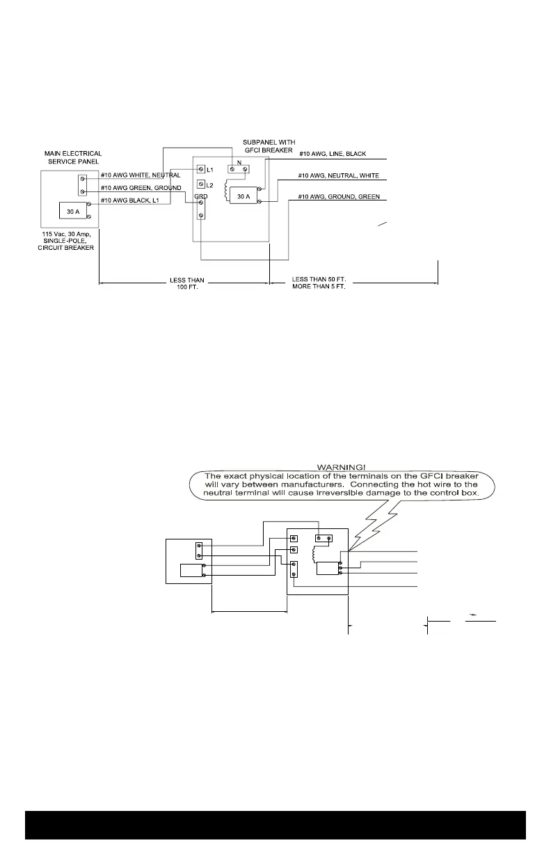
115 VOLT 30 AMP CONVERSION (PACE, STRIDE, SX & TX SPAS)
To ensure you will have an opportunity to use your spa soon after delivery, it is very important that the required
electrical service has been installed. Unless otherwise stipulated by your dealer, THIS IS YOUR RESPONSIBILITY.
IMPORTANT: All electrical circuits must be installed by a qualified, licensed electrician.
230 VOLT INSTALLATION (RELAY
®
& RHYTHM
®
AND
OPTIONAL PACE,
STRIDE, SX AND TX CONVERTED SPA
MODEL)
Your spa contains a control box designed to operate at 230V, 60Hz. Installation of a 50 amp. dedicated circuit is
required for Relay & Rhythm spas and optional for the other spa models. The control box must be hard wired directly
to a subpanel protected by a Ground Fault Circuit Interrupter (GFCI). The subpanel containing GFCI breakers
is included with the Relay & Rhythm spa models only. Purchase the subpanel from you dealer for the converted
models when converting to 230 volts.
IMPORTANT NOTE: All electrical connections to the control box must be accomplished by a qualified electrician in
accordance with the National Electrical Code and in accordance with any local electrical codes in effect
at the time and
place of
installation.
All electrical connections
must be made in
accordance with the wiring
information contained in this
manual and on the back
of the field wiring access
panel of the control box. A
licensed electrician should
install a four-wire electrical
service (two line voltages,
one neutral, one ground)
from the main electrical
service panel to the subpanel.
Your electrician should mount the subpanel in the vicinity of the spa but it should not be closer than five feet (1.5 m)
from the spa water edge (NEC 680-38 to 41-A-3).
INSTALLATION NOTE: After the spa has been installed, your electrician can connect the conduit from the subpanel
to the spa’s control box and then complete the wiring connections in the control box. NOTE: Complete step-by-ste
p
Installation and Wiring Instructions for all models are included in the Owner’s Manual.
WARNING: Removing or bypassing the GFCI breakers in the subpanel at any time will result in an unsafe spa and
will void the warranty.
Pre-Delivery Instructions Page 11
VERIFY FACTORY JUMPER
REMAINS BETWEEN “N” & “L2”
*
*
See
Owner’s Manual
for Spa Wiring
and Jumper
Configuration
CONTROL BOX
PANEL
ELECTRICAL
MAIN SERVICE
LESS THAN 100 FT.
#8 AWG RED, L2
#8 AWG BLACK, L1
#8 AWG GREEN, GROUND
#8 AWG WHITE, NEUTRAL
50A
WITHIN SIGHT OF THE SPA
THE SUB-PANEL MUST BE
MORE THAN 5 FEET
DO NOT EXCEED 50 FEET
WITH GFCI
BREAKERS
50A
SUB-PANEL
L2
GRD
L2, HOT, #8 AWG RED
L1, HOT, #8 AWG BLACK
GROUND, #8 AWG GREEN*
N, NEUTRAL, #8 AWG WHITE
L1L2
N
PERMANENTLY CONNECTED
230 VAC, 50A, 60Hz, MODELS
230VAC, 50 Amp
2-POLE
CIRCUIT BREAKER
(NON GFCI)
N
L1
GND
ILLUSTRATION
SEE WIRING
230 VAC PERMANENTLY CONNECTED SPA
L1L2
N
CONVERTED 230VAC SPA MODELS
JUMPERS REQUIRED
NO POWER
JP1
JP2
JP6
JP3
JP4
JP5
JP8
JP7
See
Owner’s Manual
for Spa Wiring
and Jumper
Configuration
 Loading...