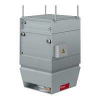
7.6 Acoustic cowl
The acoustic cowl reduces the noise level in the room; it is installed in the
Air-Injector. This does not change the outside dimensions of the Air-Injector.
Insertion attenuation is 4 dB compared with the total sound power level of each
TopVent
®
unit.
7.7 Hydraulic assembly diverting system
An assembly for the hydraulic diverting system is included in the delivery.
It consists of the following components:
■ Automatic air vent
■ Coil screw joint
■ Control valve
■ Distributor circuit screw joint
■ Flow
■ Mixing valve
■ Ball valve
■ Return
7.8 Mixing valve
Mixing valves, which are optimally matched to the units, are available for easy
installation of TopVent
®
units. They have the following specications:
■ 3-way mixing valve with modulating rotary actuator (run time 9 s)
■ Flow characteristic:
– Equal percentage control path
– Linear bypass
■ Integrated position control and response
7.9 Condensate pump
The condensate pump is installed directly under the condensate drain connection;
the supplied container is prepared for installation on the unit. It pumps the conden-
sate through a exible hose to a delivery head of 3 m, thus enabling discharge of
the condensate
■ through waste water pipes directly below the ceiling,
■ onto the roof.
7.10 Return temperature sensor
The return temperature sensor monitors the return temperature of the heating
medium.
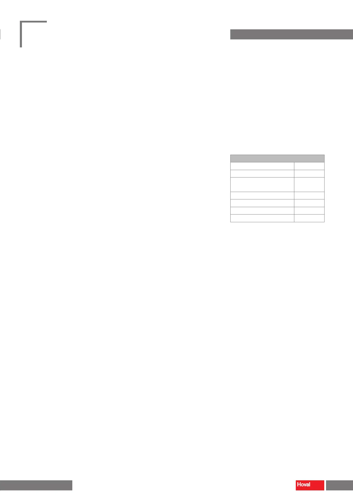
Mixing valves electrical data
Nominal voltage 24 V AC/DC
Nominal voltage frequency 50/60 Hz
Power consumption for
wire sizing
23 VA
Control signal Y 0…10 V DC
Operating range Y 2…10 V DC
Position response U 2…10 V DC
Actuator run time 9 s / 90°
Table 21: Electrical data of mixing valves (for 'Hydraulic
assembly diverting system' and 'Mixing valves')
22 23
TopVent
®
TH
|
TC
|
THC
|
MH
|
MC
|
MHC
Operating instructions
Options Options
4 218 828-en-01
 Loading...