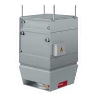
7.11 Pump control for mixing or injection system
Instead of the diverting system, a mixing or injection circuit can also be installed in
the load circuit.
Please note the following:
■ Not only the mixing valves but also the pumps in the load circuit are controlled
directly by the control block.
■ Terminals for wiring the mixing valves and the pumps in the load circuit are
located in the connection box.
■ Make sure that valves and pumps which meet the following requirements are
provided on site.
Requirements for mixing valves
■ Use 3-way mixing valves with the following ow characteristics:
– Equal percentage control path
– Linear bypass
■ The valve authority must be ≥ 0.5.
■ The maximum run time of the valve actuator is 45 s.
■ The valve actuator must be continuous, i.e. the stroke changes in proportion to
the control voltage (0…10 V DC or 2…10 V DC).
■ The valve actuator must be designed with a position response (0...10 V DC or
2…10 V DC).
■ The maximum power consumption is 20 VA.
■ Install the valve close to the unit (max. distance 2 m).
Requirements for pumps
■ Voltage ..........230 V AC
■ Current ..........up to 4.0 A
Requirements on changeover valves
■ Use changeover valves conforming to the following specication:
■ 3-way changeover valves
■ Supply voltage 24 V AC
■ 1-wire control (0/24 V AC)
■ Position response via limit switches (0°/90°)
■ Power consumption max. 44 VA
24
TopVent
®
TH
|
TC
|
THC
|
MH
|
MC
|
MHC
Operating instructions
Options
4 218 828-en-01 4 218 828-en-01
 Loading...