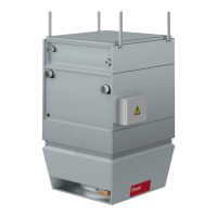
Pressure drop in kPa
0
02
04
06
08
001
021
041
061
081
002
022
042
000500540004005300030052000200510001
1.0 1.2 1.4 1.6
1.8
2.0 2.2
2.4
2.6
3.0
4.0
6AB
0
02
04
06
08
001
021
041
061
081
002
022
042
0007005600060055000500540004005300030052000200510001
1.0
1.2
1.4 1.6 1.8 2.0
2.2
2.4
2.6
3.0
4.0
6C
Water flow rate in l/h
Pressure drop in kPa
0
02
04
06
08
001
021
041
061
081
002
022
042
000900080007000600050004000300020001
1.0 1.2 1.4 1.6 1.8 2.0 2.2 2.4 2.6
3.0
4.0
9AB
0
02
04
06
08
00
02
04
06
08
00
02
04
2
1100020001000 3000 4000 5000 6000 7000 8000 9000 10000
1.0 1.2 1.4 1.6 1.8 2.0 2.2 2.4 2.6 3.0
4.0
9C
0
02
04
06
08
001
021
041
061
081
002
022
042
000210001100001000900080007000600050004000300020001
1.0 1.2 1.4 1.6 1.8
2.0
2.2
2.4
2.6
3.0
4.0
9D
Water flow rate in l/h
Fig. 21: Default settings for the balancing valves
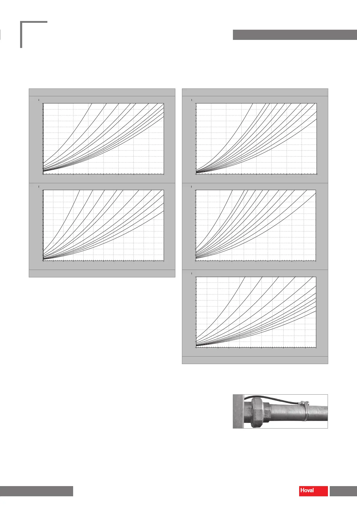
Return temperature sensor (option)
■ Install the return temperature sensor on the return line, directly after the screw
connection.
■ Attach the sensor with the clamping band.
■ Insulate the sensor.
Fig. 22: Return temperature sensor
28 29
TopVent
®
TH
|
TC
|
THC
|
MH
|
MC
|
MHC
Operating instructions
Transport and installation Transport and installation
4 218 828-en-01
 Loading...