Howden 24-07.030r04 11/25
E-series Axial Flow Cooling Fans
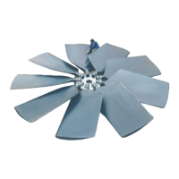
Figure 11
Tip: You may also choose to install the fan
blades onto the hub-plate before bolting the
complete impeller onto the coupling flange.
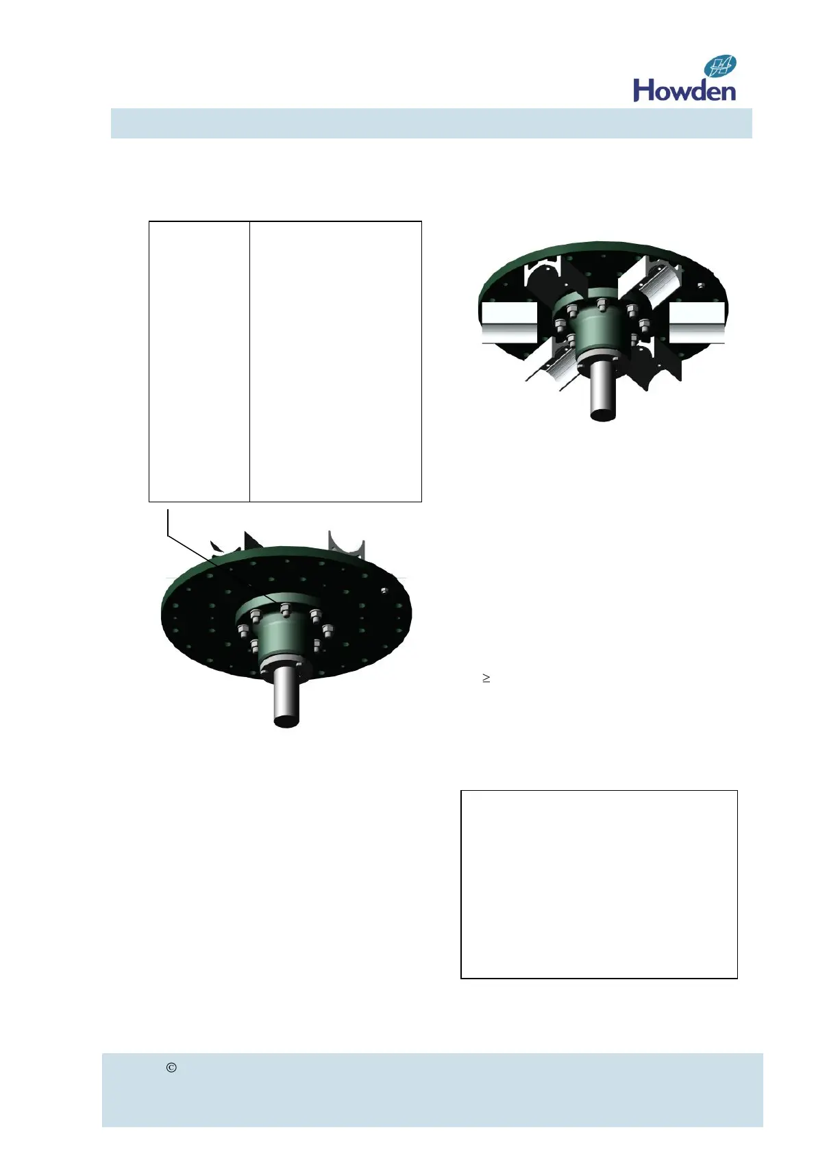
Figure 12
Tip: The hub-plate may be installed with the
clamping pieces either at the flow inlet or flow
outlet side. This may help to correctly position
the fan blades in the fan casing (see figure 12).
This configuration is only possible when the
coupling flange is fitted on the opposite side
from the lower clamping pieces or in a configu-
ration like figure 12, for impellers with a diame-
ter 9‟ (2743 mm).
If you prefer to use a configuration with the
coupling flange fitted in between the lower
clamping pieces, for impellers smaller than 9 ft.,
than please ask Howden at order placement.
Standard bolts (8.8, A3B)
Stainless steel (A4)
Nm lb.ft
75 55
185 136
360 266
625 461
1260 929
2600 1918
5500 4057
Thread
size
M12
M16
M20
M24
M30
M42
M48
Important
Impellers with a diameter smaller than
4455 mm or 14 feet are balanced
according to a certain hub-plate
configuration. Check the sticker on the
hub-plate to make sure the installation
corresponds to the applied balancing
method (refer to balancing section on
page 15).