Howden 24-07.030r04 14/25
E-series Axial Flow Cooling Fans
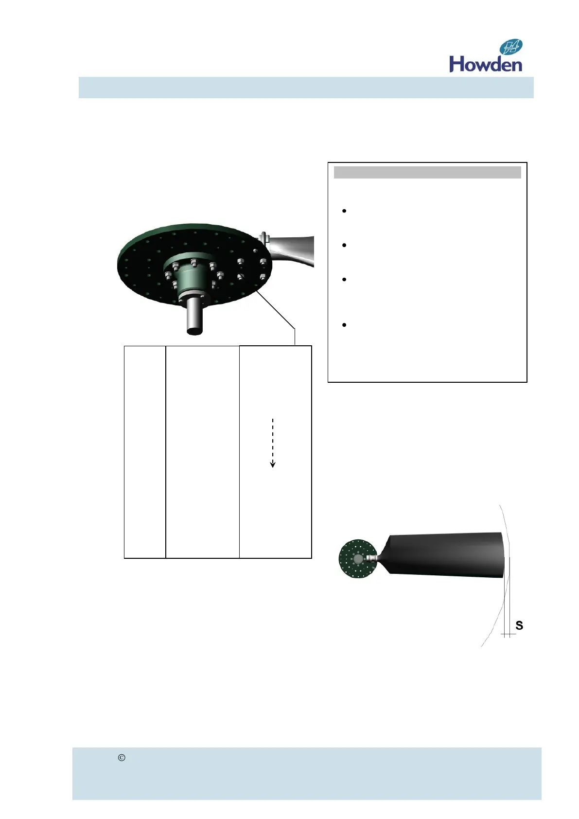
Note: the polyester stem will be com-
pressed during this operation and may pro-
duce a cracking sound.
Figure 16
h. Repeat the above operation for all blades.
i. Re-tighten the U-bolts after 50-75 hours in
operation, or 120-150 hours stand still. Do
not loosen the nuts first, but start to tighten
immediately.
j. When the blade angle has changed, the U-
bolts need to be tightened again to full
torque and also re-tightened after 120-150
hours.
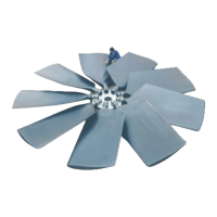
Minimum tip-clearance
Tip clearance “s” is the distance between the
blade tip and the impeller casing (figure 17).
Due to normal impeller casing tolerances the
tip clearance is not constant around the im-
peller casing.
Figure 17
Howden recommends a tip clearance of 0.5% of
the impeller diameter. Fan selections using
Howden CF-P20 software use this default stan-
dard, unless otherwise specified. Tip clearance
shall never be less than 0.25%.
WARNING
DO NOT forget to re-tighten the U-
bolts as they may loosen due to creep
of the FRP material of the blade stem.
ONLY use original Howden hardware.
The nuts are treated with special “low
friction” coating.
DO NOT re-tighten location bolts of
the lower clamping pieces (location
bolts are used in special applications
only).
After loosening and disassembling of
a U-bolt, the legs of the U-bolt have
lost the parallel shape due to
relaxation effects. That is why it is not
allowed to re-use those U-bolts.
Thread
size
M12
M16
M20
M24
M30
M36
M42
(A2, St8.8)
= Standard
Nm lb
.
ft
60 44
140 103
250 184
425 313
650 479
1100 811
1300 959
( A4)
= Optional
Nm lb
.
ft
Idem
380 280
500 369
970 715
- -