Howden 24-07.030r04 13/25
E-series Axial Flow Cooling Fans
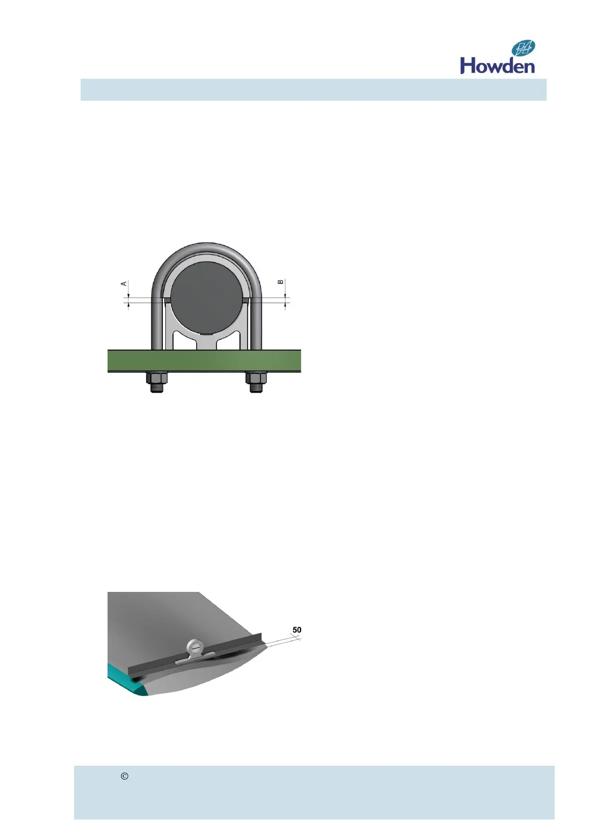
serting the outer U-bolt first. Check if the
upper clamping piece is mounted
horizontally by measuring the gap A an B
between the lower and upper clamping
piece (see figure 14).
Figure 14
c. Tighten the nuts alternating such that the
blade can still be somewhat turned in the
clamping piece.
d. Make sure that the blade stem collar is flush
against the lower clamping piece, which can
be achieved by pulling the blade outwards.
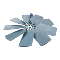
e. Place a straight edge or a sufficiently stiff
strip (at least as long as the profile width) on
top of the blade (discharge side) at about 50
mm (2 inches) from the blade profile end.
Place an inclinometer on top of the straight
edge (figure 15).
Figure 15
f. Lift the blade at the tip and rotate the blade
around its axis until the desired angle is set,
within a maximum tolerance of ± 0.5 de-
grees.
g. Re-check if the blade stem collar is flush
against the lower clamping piece.
Tighten the U-bolt nuts evenly to full torque
as shown in figure 16, starting with the U-
bolt at the collar side. Both the torque
values of our standard stainless steel (A2)
or galvanised steel (ST8.8) hardware as
well as our optional A4 stainless steel
hardware are shown. The material code A2,
St8.8 or A4 is stated on the nut. Make sure
that the blade angle does not change during
this operation (for the correct thread size
refer to table 8 on page 23).
After tightening of the nuts, the threaded
bolt ends out of the nuts shall have equal
length. The U-bolt is damaged if this is not
the case and don't fit for purpose anymore.