Howden 24-07.030r04 12/25
E-series Axial Flow Cooling Fans
Blades Installation
Impellers 4455 mm / 14 feet
Impellers up to and including a diameter of
4455 mm or 14 feet are balanced in assembly
and have a unique balancing code.
Check if the blades share the same project
number.
The blades must be positioned in the lower
clamping pieces with corresponding bal-
ancing code.
(For position of these numbers see figure 13).
Impellers > 4455 mm / 14 feet, and odd
number of blades
Impellers with an odd number of blades -
require the blades to be installed as sets.
Check if the blades share the same project
number.
The blades must be installed on a hub-
plate as sets. A blade-set share the same
2- or 3-digit figure in the balancing code
(e.g. 11A, 11B, 11C, 11D, 11E in case of a
5-bladed impeller).
(For position of these numbers see figure 13).
Impellers > 4455 mm / 14 feet, and even
number of blades
Impellers with an even number of blades re-
quire the blades to be installed in pairs.
Check if the blades share the same project
number.
The blades must be installed on the hub-
plate in pairs, with the paired blades posi-
tioned opposite each other. Always position
blade “A” facing blade “B”. Pairs share the
same 2- or 3-digit figure in the balancing
code (e.g. 31A facing 31B, 32A facing 32B,
33A facing 33B in case of a 6-bladed im-
peller).
(For position of these numbers see figure 13).
Note: For impellers > 4455 mm / 14 feet the
blade sets can be installed on any position of
a fan hub, provided that the blade sets will be
installed in the sequences spelled out in this
paragraph.
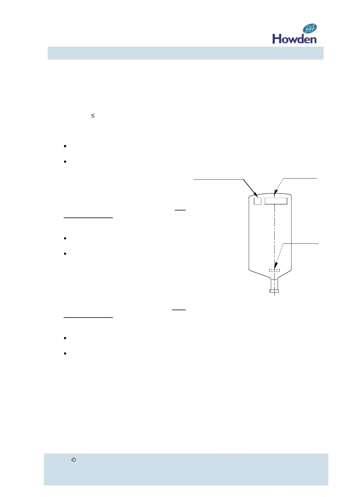
The blades are marked with a unique blade
number, a project number and a balancing
code (see figure 13).
Figure 13
Procedure:
a. Place a blade in a suitable lower clamping
piece of the hub plate, considering the in-
stallation rules as described in this para-
graph.
b. Place the upper clamping pieces over the
blade stem and insert the U-bolts through
the holes of the hub-plate. Place the
washers and hand-tighten the nuts just
enough to keep the blade in place. For the
standard configuration (blades on top of
hub plate) we recommend to insert and
tighten the inner U-bolt first (next to the
collar). When the blades are hanging un-
derneath the hub-plate we recommend in-