Howden 24-07.030r04 9/25
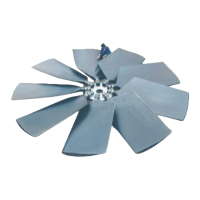
E-series Axial Flow Cooling Fans
Coupling flange with parallel bore
a) Check if the shaft and bore diameters are
according to specification. The standard
execution has a H7 fit.
b) Slightly lubricate the shaft, the key, and
the bore of the hub with grease.
c) Locate the key (19) into the drive shaft
(figure 7).
d) To slip the coupling flange over the shaft
we advise you to uniformly heat up the
coupling flange up to maximum 120 °C
(248 °F) by means of a hot plate, electric
induction or oil bath, until a 0.15mm dif-
ference in diameter is reached. Wear
protective gloves during this operation.
e) Slip the coupling flange (11) onto the
drive shaft and check the key for proper
fit. Be sure the coupling flange is com-
pletely through the shaft against the shaft
shoulder.
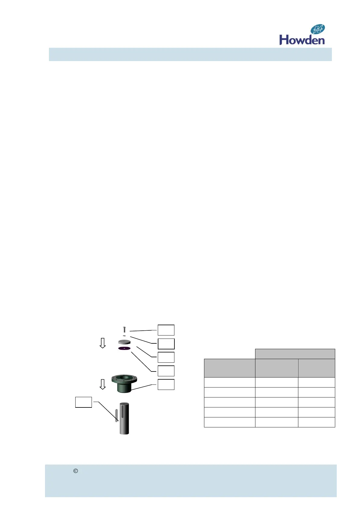
f) For reverse coupling flange configuration:
(e.g. impeller hanging below the driver)
Install the retaining plate (14) with gasket
(17) and secure it to the shaft with the
lock washer (16) and the central bolt
(15). Supply of retaining plate items 14,
15, 16 and 17 by Howden is optional.
Item 19 (key) is not supplied by Howden.
For torque values of the retaining plate
bolts see table 7 on page 22.
Figure 7
Coupling flange with tapered bushing
(Supply of coupling flange with tapered
bushing is optional).
a) Do not lubricate bushing, coupling flange
bore or hardware. Use of lubricants can
cause coupling flange damage.
b) Slip the bushing onto the drive shaft and
check the key (19) for proper fit (figure 8
on page 10). Be sure the shaft is com-
pletely through the bushing. Keep a bolt
length as minimum distance X between
bolts (13) and flange of the drive (figure 9
on page 10).
c) Lock the bushing on the shaft by tighten-
ing the setscrew in the flange. Support
the bushing with a sleeve to prevent it
from sliding down during assembly.
d) Install the coupling flange onto the bush-
ing. Start bolts (13) by hand turning just
enough to engage threads.
e) Keep tightening them as equally as
possible, in several steps, while drawing
the hub onto the bushing until the bush-
ing tightly grips the shaft.
f) Tighten the bolts to the torque shown in
table 3. Do not over-torque. Excessive
torque can cause coupling flange or
bushing damage. Some gap must remain
between the flange of the bushing and
coupling flange in properly tightened as-
sembly.
Torque value for bolts
tapered bushing to coupling flange
Table 3