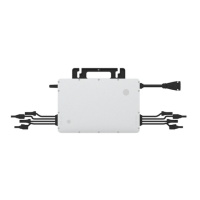
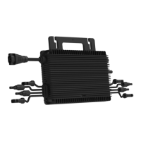
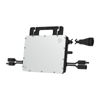
This document describes the Hoymiles HMS-1600D-4T, HMS-1800D-4T, and HMS-2000D-4T single-phase microinverters, which are designed to convert direct current (DC) from photovoltaic (PV) modules into alternating current (AC) for feeding into the public grid. These are 4-in-1 microinverters, meaning each unit connects to four PV modules.
Function Description
The microinverter system is composed of a group of microinverters that convert DC power from PV modules into AC power that meets grid requirements. The AC power is then fed into the grid via a meter. Each microinverter operates independently, ensuring maximum power generation from each connected PV module. This independent operation provides high flexibility and reliability, allowing for direct control over the production of each PV module.
The Hoymiles HMS-2000D-4T series microinverters feature module-level monitoring. Data from the microinverters are collected by a Hoymiles gateway DTU (Data Transfer Unit) via wireless transmission and then sent to the Hoymiles S-Miles Cloud monitoring platform. The system utilizes Maximum Power Point Tracking (MPPT) for each PV module, which optimizes energy harvest, especially in partial shade conditions. With dual MPPT, if one MPPT fails or is shaded, the other can still operate the unshaded string at maximum efficiency. The microinverter operates with low DC voltage (a few dozen volts), significantly reducing safety hazards.
The HMS-2000D-4T series microinverters incorporate Sub-1G wireless technology for communication with the DTU gateway. This technology offers more stable communication, a substantially longer range (1.5 to 2 times that of 2.4GHz Wi-Fi or Zigbee), and better interference suppression performance, making it well-suited for rooftop PV power stations, including industrial or commercial applications. It also boasts lower power consumption compared to Wi-Fi or Zigbee.
Important Technical Specifications
The microinverters are available in three models: HMS-1600D-4T, HMS-1800D-4T, and HMS-2000D-4T, with maximum output powers of 1600 W, 1800 W, and 2000 W, respectively.
Input Data (DC):
- Commonly used module power:
- HMS-1600D-4T: 320 to 540+ W
- HMS-1800D-4T: 360 to 600+ W
- HMS-2000D-4T: 400 to 670+ W
- Maximum input voltage: 65 V
- MPPT voltage range: 16-60 V
- Start-up voltage: 22 V
- Maximum input current:
- HMS-1600D-4T: 4 × 14 A
- HMS-1800D-4T: 4 × 15 A
- HMS-2000D-4T: 4 × 16 A
- Maximum input short circuit current: 4 × 25 A
- Number of MPPTs: 2
- Number of inputs per MPPT: 2
Output Data (AC):
- Maximum continuous output power (VA): 1600 (HMS-1600D-4T), 1800 (HMS-1800D-4T), 2000 (HMS-2000D-4T)
- Maximum continuous output current (A):
- HMS-1600D-4T: 7.27 (220V), 6.96 (230V), 6.67 (240V)
- HMS-1800D-4T: 8.18 (220V), 7.83 (230V), 7.50 (240V)
- HMS-2000D-4T: 9.09 (220V), 8.70 (230V), 8.33 (240V)
- Nominal output voltage/range: 220/180-275 V, 230/180-275 V, 240/180-275 V (ranges may vary based on local requirements)
- Nominal frequency/range: 50/45-55 Hz or 60/55-65 Hz (ranges may vary based on local requirements)
- Power factor (adjustable): > 0.99 default, 0.8 leading ... 0.8 lagging
- Total harmonic distortion: < 3%
- Maximum units per branch:
- HMS-1600D-4T: 4 units (220V, 230V, 240V)
- HMS-1800D-4T: 3 units (220V), 4 units (230V, 240V)
- HMS-2000D-4T: 3 units (220V, 230V, 240V)
Efficiency:
- CEC peak efficiency: 96.70% (HMS-1600D-4T), 96.50% (HMS-1800D-4T, HMS-2000D-4T)
- Nominal MPPT efficiency: 99.80%
- Night power consumption: < 50 mW
Mechanical Data:
- Ambient temperature range: -40 to +65 °C
- Dimensions (W × H × D): 310 x 185 x 40.6 mm
- Weight: 4.5 kg
- Enclosure rating: Outdoor-IP67 (NEMA 6)
- Cooling: Natural convection - No fans
Features:
- Communication: Sub-1G
- Topology: Galvanically Isolated HF Transformer
- Monitoring: S-Miles Cloud
- Compliance: UL 1741, ABNT NBR 16150:2013, ABNT NBR 16149:2013
Usage Features
Installation:
- Installation must be performed by qualified technicians.
- The microinverter and all DC connections should be installed under the PV module to avoid direct sunlight, rain, snow, and UV exposure. The silver side of the microinverter should face up towards the PV module.
- A minimum of 2 cm of space around the microinverter enclosure is required for ventilation and heat dissipation.
- The microinverter should be kept in a well-ventilated place and away from flammable substances.
- AC Trunk Cable (12AWG or 10AWG) and AC Trunk Connectors are used for connection to the power distribution box.
- Grounding can be done directly via the earth wire in the AC cable, or optionally with grounding brackets for specific regional requirements.
- The installation process involves marking positions, fixing screws on the rail, hanging and tightening the microinverter, and then planning and building the AC Trunk Cable by disassembling and reassembling connectors and end caps.
- After AC connection, any vacant AC Trunk Ports must be sealed with an AC Trunk Port Cap for water and dust proofing.
- An installation map is created by affixing serial number labels from each microinverter to the corresponding locations on the map.
- PV modules are mounted above the microinverter and their DC cables are connected to the microinverter's DC input side.
- The system is energized by turning on the AC breaker of the branch circuit and then the main AC breaker of the house. The system typically starts generating power within two minutes.
- A monitoring system is set up using the DTU and S-Miles Cloud platform, following specific user manuals and quick installation guides.
Operation:
- The LED indicator provides status information:
- Start-up: Flashing green five times (0.3s gap) indicates success; flashing red five times (0.3s gap) indicates failure.
- Operation: Fast green flashes (1s gap) indicate power production; slow green flashes (2s gap) indicate power production with one abnormal input; red flashes (0.5s gap) indicate invalid AC grid or hardware failure; red flashes (1s gap) indicate no power production due to invalid AC grid; solid red indicates hardware failure.
- Other: Alternating red and green flashes indicate firmware is broken.
- The microinverter is powered by the DC side. If the LED is off, check the DC side connection.
Maintenance Features
Troubleshooting:
The manual provides a comprehensive troubleshooting list with alarm codes, statuses, and handling suggestions.
- Over temperature protection (Code 121): Check ventilation and ambient temperature; improve ventilation if necessary. If the problem persists, contact support.
- Shut down by remote control (Code 124): Check zero export management and manual shutdown status.
- Grid configuration parameter error (Code 125): Check and upgrade grid configuration parameters.
- Firmware error (Code 127): Check firmware, communication between DTU and monitoring system, and DTU and microinverter.
- Abnormal bias (Code 129): If occasional, no special treatment. If frequent, contact support.
- Offline (Code 130): Verify normal microinverter operation (DC voltage, LED status), SN matching monitoring platform, and communication status between DTU, monitoring system, and microinverter.
- Grid overvoltage/undervoltage (Codes 141, 143): If occasional, microinverter recovers automatically. If frequent, check grid voltage range and contact local power operator or adjust grid profile via monitoring system.
- Grid overfrequency/underfrequency (Codes 144, 145): Similar to voltage issues, check frequency range and contact local power operator or adjust grid profile.
- Rapid grid frequency change rate (Code 146): Similar to frequency issues, check change rate and contact local power operator or adjust grid profile.
- Power grid outage/disconnection (Codes 147, 148): Check AC switch, branch breaker, and AC wiring.
- Island detected (Code 149): If occasional, microinverter recovers. If frequent on all microinverters, contact local power operator. If on only some, contact support.
- Input overvoltage/undervoltage (Codes 205-208, 215-222): Ensure PV module open-circuit voltage is within specified limits. If within normal range, contact support.
- No input (Codes 209-212): Confirm PV module connection to the port and check DC cable connection.
- Abnormal wiring (Codes 213, 214): Check DC connections on specified ports and DC extension cable.
- Device failure (Codes 301, 314): If occasional, no special treatment. If frequent, contact support.
- Do not attempt to repair the microinverter yourself. If troubleshooting fails, return it to the factory for replacement.
Routine Maintenance:
- Only authorized personnel should perform maintenance.
- Always use personal protective equipment during maintenance.
- Regularly check environmental conditions to ensure they haven't changed and equipment is not obstructed or exposed to adverse weather.
- Do not use equipment with detected problems; restore working conditions after fixing faults.
- Conduct annual inspections and clean equipment with a vacuum cleaner or special brushes.
- Do not dismantle or repair the microinverter; no user-serviceable parts inside.
- The AC output wiring harness cannot be replaced; if damaged, the equipment should be scrapped.
- Maintenance must be carried out with the equipment disconnected from the grid and PV modules shaded or isolated.
- Never clean with filamentary or corrosive rags to avoid corrosion and electrostatic charges.
- All repairs should use eligible spare parts.
- If all microinverters are connected to a DTU-Pro-S, the DTU can limit output power imbalance between phases to below 3.68 kW if required.
- Each branch should have a circuit breaker; a central protection unit is unnecessary.
Microinverter Replacement:
- Removal: De-energize the AC branch circuit breaker, remove and cover the PV module, check for current in DC wires, remove DC and AC connectors with disconnect tools, loosen fixing screws, and remove the microinverter from the racking.
- Replacement in monitoring platform: Note the new microinverter's serial number, install the replacement unit, then access the "Device List" on the monitoring platform, select "Device Maintenance," choose "Replace Device," input the new SN, and confirm.
Decommissioning, Storage, and Transportation:
- Decommissioning: Disconnect from DC input and AC output, remove all cables, and remove the microinverter from the frame. Pack in original packaging or a suitable carton box (max 5 kg, fully closed).
- Storage and Transportation: Hoymiles packages are designed for protection during transport. Examine components upon receipt for damage or missing parts and contact the carrier or supplier if issues are found. Storage temperature range is -40°C to 85°C. Store indoors with good ventilation if not used immediately or for long periods.
- Disposal: Dispose of microinverters properly according to local regulations to prevent environmental harm.