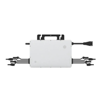
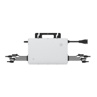
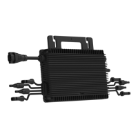
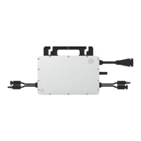
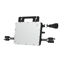
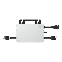
This document describes the Hoymiles Single-phase Microinverter, specifically the HMS-1600-4T, HMS-1800-4T, and HMS-2000-4T models. These microinverters are designed to convert direct current (DC) from photovoltaic (PV) modules into alternating current (AC) for feeding into the public grid. The system is configured for 4-in-1 microinverters, meaning each microinverter connects to four PV modules.
Function Description
The core function of the Hoymiles microinverter system is to facilitate the generation of electricity from solar panels and integrate it into the power grid. Each microinverter operates independently, ensuring that the maximum power is generated from each individual PV module. This independent operation is crucial for system reliability and flexibility, as it means that if one PV module fails or is shaded, the performance of other modules in the array will not be affected. This module-level Maximum Power Point Tracking (MPPT) boosts the overall power production of the system.
The microinverter continuously monitors the current, voltage, and power of each connected module, enabling detailed module-level data monitoring. This granular monitoring capability allows for precise performance tracking and easier identification of issues. A significant safety feature of these microinverters is that they operate with a low DC voltage (less than 80 volts), which substantially reduces potential safety hazards compared to higher voltage systems.
For data collection and system oversight, Hoymiles microinverters utilize a wireless transmission system to send data to a Hoymiles Data Transfer Unit (DTU). The DTU then relays this information to the Hoymiles monitoring platform, S-Miles Cloud, providing users with comprehensive insights into their system's performance.
Usage Features
The Hoymiles microinverter system is designed for straightforward installation and robust operation. The microinverters are typically installed underneath PV modules to ensure they remain in the shade, preventing power derating due to increased internal temperature. Proper ventilation and a minimum clearance of 2 cm around the enclosure are required for optimal heat dissipation.
The system employs Sub-1G wireless technology for communication with the DTU. This technology offers several advantages over 2.4 GHz bands like Wi-Fi or Zigbee, including a substantially longer transmission range (1.5 to 2 times greater) and enhanced interference suppression performance. This makes Sub-1G particularly well-suited for industrial or commercial PV power plants and rooftop installations where stable communication over distance is essential. Additionally, Sub-1G wireless communication is more power-efficient, contributing to lower overall system consumption.
The microinverters are housed in an IP67 (NEMA 6) enclosure, providing high reliability and protection against environmental factors. They also feature 6000 V surge protection, enhancing their durability and lifespan. The power factor is adjustable, ranging from 0.8 leading to 0.8 lagging, offering flexibility for grid integration requirements.
Installation involves marking positions on the rail, fixing screws, and then hanging and tightening the microinverter. Grounding can be achieved directly through the AC cable, which contains an earth wire, or via optional grounding brackets for regions with specific requirements. The AC Trunk Cable, which connects the microinverters to the power distribution box, is selected based on the spacing between microinverters to ensure proper matching of connectors. The process includes disassembling, preparing, and installing segments of the AC Trunk Cable, ensuring proper wire insertion (L, N, PE) and tightening of screws and caps for water and dust proofing. Once the AC connections are complete and PV modules are connected, the system is energized by turning on the AC breakers, and power generation typically begins within two minutes. A dedicated monitoring system is then set up using the DTU and S-Miles Cloud platform.
Maintenance Features
Routine maintenance of the Hoymiles microinverter system is crucial for ensuring its long-term performance and safety. Maintenance operations should only be carried out by authorized and trained personnel who are responsible for reporting any anomalies. Personal protective equipment, such as gloves and goggles, must be used during maintenance.
Regular checks of environmental conditions are recommended to ensure they remain suitable and that the equipment is not obstructed or exposed to adverse weather. If any operational anomalies are detected, the equipment should not be used until the fault is fixed and working conditions are restored. Annual inspections of various components are advised, along with cleaning the equipment using a vacuum cleaner or special brushes. It is explicitly stated that cleaning should not be done with rags made of filamentary or corrosive materials to prevent corrosion and electrostatic charges.
Troubleshooting guidance is provided through a list of alarm codes and corresponding handling suggestions. These suggestions range from checking ventilation and ambient temperature for over-temperature protection alarms to verifying grid configuration parameters for grid-related errors. For communication issues, checking DTU and monitoring system connections, as well as firmware status, is recommended. In cases of input overvoltage or undervoltage, checking the PV module's open-circuit voltage is advised. For device failures or persistent issues, contacting the dealer or Hoymiles technical support team is the recommended course of action.
A critical safety instruction is that users should not attempt to dismantle or repair the microinverter themselves, as there are no user-serviceable parts inside for safety and insulation reasons. All repairs must be performed by a licensed contractor or authorized Hoymiles service representative using qualified spare parts. If the AC output wiring harness (AC drop cable) is damaged, the equipment should be scrapped as it cannot be replaced. Maintenance operations must always be carried out with the equipment disconnected from the grid (power switch open) and the PV modules shaded or isolated, unless otherwise specified.
For microinverter replacement, the process involves de-energizing the AC branch circuit breaker, removing and covering the PV module, checking for current in DC wires, disconnecting DC and AC connectors, loosening fixing screws, and finally removing the microinverter from the racking. On the monitoring platform, the new microinverter's serial number is inputted to update the station. The DTU-Pro-S, when connected to all microinverters, can limit the output power imbalance between phases if required, further enhancing system stability and compliance.
When decommissioning, the inverter should be disconnected from DC input and AC output, all cables removed, and then the microinverter removed from its frame. It should be packed in its original packaging or a suitable carton box for storage and transportation. The storage temperature range is -40 to 85°C. Proper disposal of microinverters in accordance with local regulations is emphasized to prevent environmental harm.